Section 1
P2 Technology for Common Metal Finishing Processes
1.1 INTRODUCTION
1.1.1 How the information is arranged
Section 1 contains an update to the original Bluebook, which is now presented in its entirety in Sections 2 through 8.
In the original Bluebook, technical information is arranged in sections covering specific topic areas, such as waste
reduction, chemical recovery, and bath maintenance. Each section includes discussions of all of the technologies
relevant to the topic, such as ion exchange, evaporation, or reverse osmosis. Information on each of the major
plating baths or processes (nickel, copper, hard chrome, anodizing etc.) is dispersed throughout the technology
discussions.
In Section 1, the order has been rearranged. Each plating bath is now discussed fully in a subsection of its own.
Grouping the discussion topics according to bath type has two main advantages:
- It enables users to develop a comprehensive strategy for upgrading each of the processes carried out in their facilities.
- It helps users appreciate which of the different variants of each pollution control technology are appropriate for the specific process they are examining.
References cited in Section 1 are indentified in footnotes. References for Sections 2 through 8 are found in the Reference section at the end of the book.
1.1.2 Information sources
The information presented in Section 1 is derived from various sources, including:
- the original Bluebook
- technical journals
- EPA and state environmental agency reports
- supplier's literature
- data collected from 1997 through 2008 from metal finishing facilities throughout the U.S. in conjunction with:
- the Strategic Goals Program (SGP, 1997 – 2001)
- the Benchmarking Metal Finishing study (conducted in 1999, updated in 2003)
- Surface Technology Environmental Resource Center (STERC) surveys (2002 – 2008)
The Benchmarking Metal Finishing study gathered information from 160 participants, who described process-specific pollution prevention practices that have worked in their shops. Most of these suggestions are practical and very cost effective to implement and many of them have been included in this update. This information is further supported by SGP data that were submitted by many of the survey participants and other facilities from 1997 through 2008.
In many cases, new technologies or variations of existing technologies have emerged since the publication of the Bluebook in 1994. A number of demonstration projects conducted since then have also provided very useful information for evaluating both technical capabilities and costs. This edition incorporates insights gleaned from the most recent sources.
1.1.3 Section format
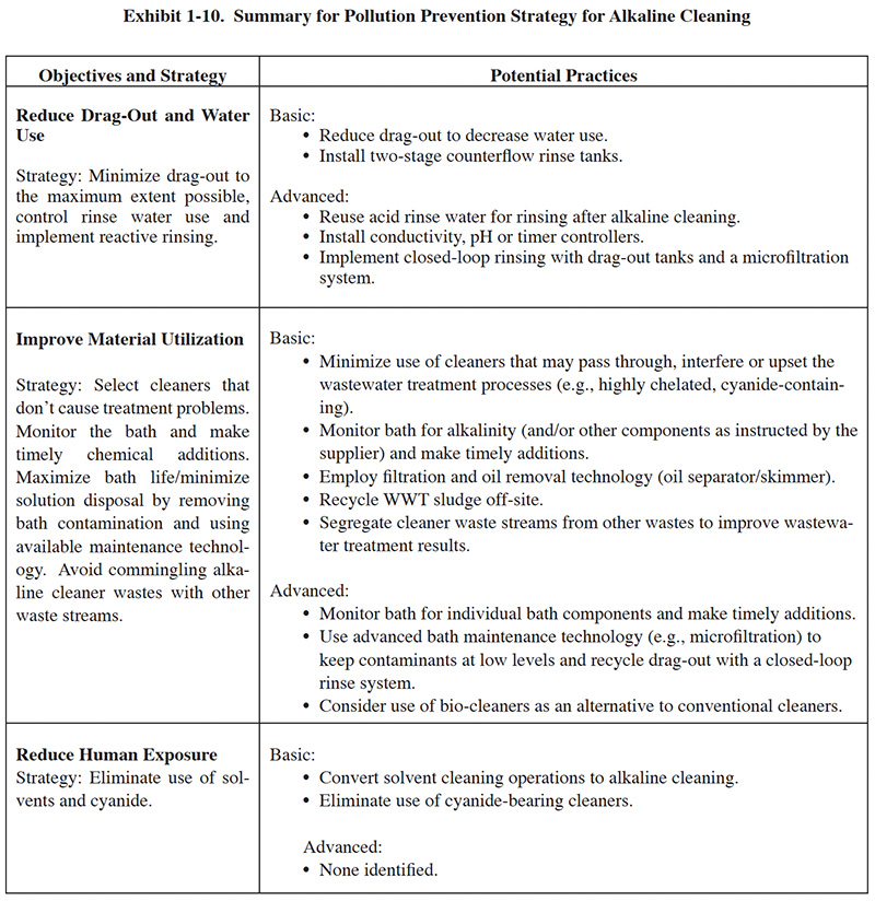
Each process section has a similar format. Following a general overview, a set of basic pollution prevention objectives are presented in the left-hand column of a summary table, with each objective accompanied by a recommended strategy for attaining it. In general, the basic objectives include:
- Reducing dragout and water use
- Improving material utilization
- Reducing human exposure
1.2 RINSING
Product quality and operating costs are both highly dependent on effective rinsing. Inadequate rinsing causes dragout carryover which contaminates downstream process solutions and can cause misplated parts. Excessive and/or inefficient use of rinse water increases water use costs, including the costs of the raw water and chemical waste treatment. With any plating operation, there is an optimal range of rinse water use that can be attained by using the right equipment, configuration and procedures.
A significant portion of the original Bluebook is devoted to best practices for dragout reduction and rinsing (see Section 3). All of that information is still valid. Presented here is:
- status report on water use trends,
- good practices reminder,
- refocus on total dissolved solids as a control parameter, and
- update on rinse controller technology.
1.2.1 Water Use Trends
Water use by U.S. metal finishing shops has decreased significantly over the past 30 years. In the late 1970s, EPA
conducted wastewater sampling at electroplating facilities as part of the rulemaking process for wastewater
standards ("effluent guidelines"). Data from the supporting EPA document4 indicate that
the average discharge for facilities in their sample population (25 facilities) was 109,000 gallons per day (or
28,340,000 gallons per year).
4(Development Document for Existing Source Pretreatment Standards for
the Electroplating Point Source Category, August 1979 (EPA 440/1-79/003)
New federal wastewater limits, went into effect in 1984. Most U.S. plating shops reduced water use as part of their overall strategy to meet the new limits By reducing water use, facilities were able to save significantly on both capital and operating costs for wastewater treatment, since both aspects of costs are closely related to the volume of wastewater flow. These reductions were relatively easy to attain. Since there had previously been little or no regulatory or economic motive to lower water use, most facilities were using more water than necessary. Therefore, basic measures, such as installing flow restrictors and turning off free-running rinses during non-production times, cut water use by 50% or more for many shops. Some facilities had already installed counterflow rinse systems, but according to the EPA development document, in 1979 the majority of plants relied on single rinse tanks.
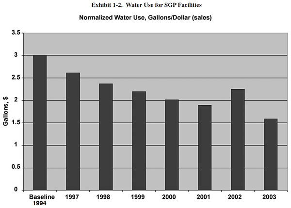
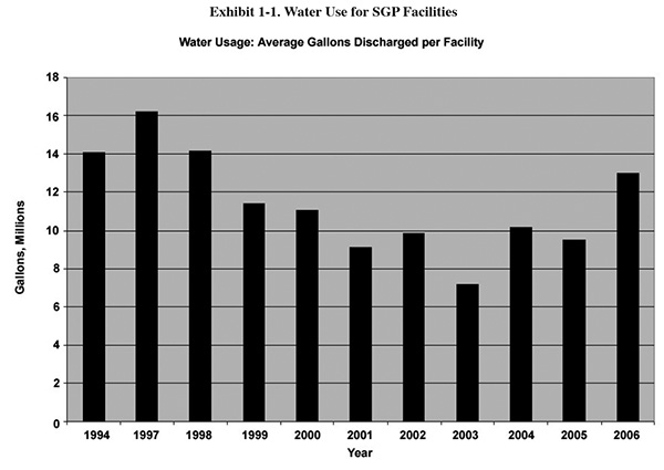
The Bluebook survey (1993) asked facilities which year they installed their wastewater treatment system. 70% of the
respondents indicated that they had a system in place by 1985, and 95% had one installed by 1990. By 1994, the
baseline year for the Strategic Goals Program (SGP)5, most plating shops had made decent
progress on water use reduction, again mainly to reduce capital and operating costs for waste treatment. Exhibit 1-1
is a graph showing the average flow for SGP facilities for 1994 and 1997 through 2006. A comparison of these flow
rates to those found in the EPA development document suggests that the industry significantly cut water use by 1994,
and made further gains through about 2003. The values here are not normalized and therefore don't account for
changes in production. However, Exhibit 1-2 shows normalized values for approximately the same time period, and it
suggests approximately the same trend (2004 to 2006 were not calculated because a much smaller number of facilities
submitted SGP data in those years).
5(More information on the SGP can be found at
www.strategicgoals.org)
How and why did facilities reduce water use from 1994 through 2003? The "how" is pretty easy to answer. Efficient rinsing systems, consisting of multiple rinse tanks and control mechanisms can reduce water use by a factor of several times, compared to the practices that were common in 1979. Although industry made significant progress by 1994, there was still plenty of low hanging fruit. Presumably, more and more facilities took advantage of this situation.
The "why" is more difficult to answer. There are most likely a number of reasons for this improvement. Cost savings was the most likely motivator. Water and sewer charges increased during those 10 years, as publicly owned treatment works (POTWs) upgraded their facilities and passed along price increases to industry. This trend is reflected in the SGP data, which show a 24% increase in the median water/sewer price from 2000 to 2006 (from $3.64 to $4.50 per 1,000 gal).
Another potential stimulus for water use reduction is the "green" movement that has impacted nearly all
sectors of U.S. industry. Metal finishers were sympathetic to the goals of the green movement, as evidenced by their
widespread participation in the SGP (over 400 SGP companies). Another factor is the improvement in information
access made possible by the Internet. Industry now has quick access to free pollution prevention and compliance
assistance information such as the Surface Technology Environmental Resource Center
(STERC)6. Also, the Internet makes it easier to locate and communicate
with consultants and vendors that can assist with pollution prevention.
6(An EPA-sponsored compliance assistance center (www.sterc.org).)
So, what happened following 2003 (see Exhibit 1-1)? It is difficult to say with certainty, because we are talking
about a relatively short time period, and it may just be an anomaly of the data (fewer companies submitted SGP data
after 2003 and perhaps a disproportionate percentage of low discharge facilities dropped out of the program). On the
other hand, although it may be just coincidental, 2003 was the year that EPA decided not to impose the additional
wastewater regulations on the electroplating industry that had been proposed under the Metal Products
and Machinery Category.7 After a close call with some very stringent
standards, some facilities may have eased up a bit. At any rate, the recent uptrend in water use will probably be
erased over the next several years as industry is forced to squeeze down further on operating costs in order to
remain competitive.
7(The Metal Products and Machinery (MP&M) regulation establishes national
technology-based limits on pollutants in wastewater discharges from facilities that manufacture, rebuild or
maintain metal parts, products, or machines. The proposed rule (Jan. 2001) included electroplating
operations, however in 2003 this sector was dropped from the rule (see http://www.epa.gov/guide/mpm).)
1.2.2 Overview of Best Practices for Rinsing
The optimal rinse system will vary from facility to facility due to variables such as part size/shape, level of automation and other site-specific factors. However, in each situation, if each of the following elements is present, rinse water use will be close to optimal:
- Multiple rinse tanks. Multiple rinse tanks plumbed in a counterflow configuration can reduce water use by 90% or more. A simple calculator, available free on-line, can be used to evaluate the impact of various rinsing strategies (more on this below).
- Water control. Any methodology that closely matches water use and workload will increase the efficiency of your rinse system. Flow restrictors as a standalone method are not sufficient, except on automated lines that are in continuous use. Examples of viable control methods include timer and conductivity controllers and optical sensors, which are used on conveyor lines (more on controllers below).
- Water circulation. If you have poor mixing in your rinses, you are wasting water. Proper plumbing of the tanks will minimize short circuiting. Air or mechanical agitation (e.g., pumping) will eliminate the problem altogether.
- Standard procedures. Skipping stages in multiple tank arrangements is the most common rinse crime. Other forms of malpractice include sabotaging controllers and using supplementary water sources, such as a hose. Rules for rinsing should be established and enforced by management. Rinse tanks should be checked on a scheduled basis for total dissolved solids (TDS) concentration (more on TDS below).
Each of these factors is covered in detail in the original Bluebook. Some additional details on several of these items are presented in this update.
On July 1, 2008, EPA published the National Emission Standards for Hazardous Air Pollutants for Plating
and Polishing Operations.8 This rule impacts many metal finishing operations (EPA
estimates 2,900 facilities). It applies to facilities with plating, polishing or thermal spray processes that
contain cadmium, nickel, lead, manganese and/or chromium. (The rule will not apply to
chromium anodizing and electroplating, which are coverered under a previous rule.)
8(National Emission Standards for Hazardous Air Pollutants: Area Source
Standards for Plating and Polishing Operations; Final Rule, Federal Register July 1, 2008.)
With this regulation EPA did not establish emission limits for plating and polishing operations as they did with chromium plating, but instead required plating and polishing facilities to implement specific pollution prevention (P2) and control practices that are related to air emissions, dragout and rinsing:
- minimize bath agitation when removing tank objects;
- maximize dripping of bath solution back into the tank by extending drip time when removing the tank objects and using drain boards (i.e., drip shields);
- optimize the design of barrels, racks, and parts to minimize dragout of bath solution, and
- use a wetting agent or fume suppressant in non-cyanide electroplating baths.
Therefore, affected facilities should also incorporate theses practices into their dragout control and rinsing systems.
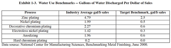
1.2.3 Water Use Benchmarks
How does your water use compare with that of other shops? One way to find out is to compare your data with industry
benchmarks. In 2000, NCMS published a benchmarking report9 (the benchmarks were updated in 2003)
that covered various metrics, including water use, metals discharged, sludge generation, and energy use.
9(National Center for Manufacturing Sciences, Benchmarking Metal Finishing, June
2000. Available at www.sterc.org.)
A unique aspect of the study results is that they account for the types of plating processes employed. For example, there are separate benchmarks for hard chromium plating, decorative chromium plating, nickel plating, zinc rack plating zinc barrel plating, anodizing, etc. The benchmarks also account for differences between certain sectors such as the auto manufacturing and fastener plating sectors. Therefore, the benchmarks can be tailored to any plating operation, even when multiple processes are present.
Water use benchmarks normalized to sales for common metal finishing processes are shown in Exhibit 1-3. The target benchmarks are the average water use for companies in the lower quartile (i.e. the best 25%).
The Strategic Goals Program (SGP) incorporated the benchmarks from this study into its program. Companies that participate in SGP automatically receive benchmark reports that show how well they measure up. These reports are particularly useful for identifying areas where significant progress can be made. For example the reports indicated how much money could be saved annually by meeting the benchmarks. You can view benchmarking reports at www.strategicgoals.org (select facility reports from the menu, and then choose "Benchmarking Analysis" on the subsequent page).
1.2.4 Using Total Dissolved Solids (TDS) as a Control Parameter for Water Use
In order to optimize rinse water use, finishers need data. Specifically, finishers should know:
- the quality of their raw water supply
- the quantity of dragout generated by various parts and fixturing used
- target levels for rinse water quality and associated part cleanliness
A relatively easy and inexpensive means for generating these data involves measurement of total dissolved solids (TDS). In a matter of hours a finisher can generate data that are as useful as results generated by days of expensive consulting and laboratory work.
TDS is present in all natural waters. Typically, tap water has a TDS content of 100 to 400 mg/l, most of which is hardness (principally calcium and magnesium and associated anions). When water is used for rinsing, the TDS concentration increases significantly due to the presence of the plating chemicals that are washed off the parts. Therefore, rinse tanks must be flushed with "clean" water during processing. Good rinsing is necessary to prevent staining and other plating problems and to prevent cross contamination of process tanks. The "cleanliness" of rinse water can be measured by analyzing for TDS. The acceptable level of TDS varies depending on factors such as intermediate vs. final rinsing, type of finish, type of parts, etc. For example, rinsing following an acid dip may be adequate at 1,000 mg/l TDS, whereas rinsing following bright plating may require a TDS of 50 mg/l or lower. Some tap waters may not be sufficiently low in TDS for rinsing after bright plating applications, thus requiring processing (e.g. by ion exchange or reverse osmosis) of the tap water prior to use.
TDS measurements are usually made in a laboratory by filtering and then evaporating water and weighing the residue. A rapid TDS measurement can be made using specific-conductance measurements (a hand-held or "pocket" TDS instrument can be purchased for under $50). Such measurements indicate the capacity of a sample to carry an electrical current, which is in turn related to the concentration of ionized substances in the water, in units of milligrams per liter (mg/l). Most dissolved inorganic substances are in the ionized form and therefore contribute to specific conductance. Although this method provides only approximate TDS values, if it is properly used, it can serve as a guide to rinse water quality.
More sophisticated measuring devices can also be used to generate rinse water data with actual specific conductance readings, in units of microsiemens per cm (µS/cm) or the equivalent micromhos/cm (µmhos/cm). For practical purposes, you can convert µS/cm (or µmhos/cm) to mg/l of TDS by dividing by two (alternatively, multiple mg/l of TDS by 2 to arrive at µS/cm of specific conductance). For example, 1,000 µS/cm is approximately equal to 500 mg/l TDS.
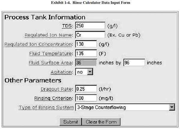
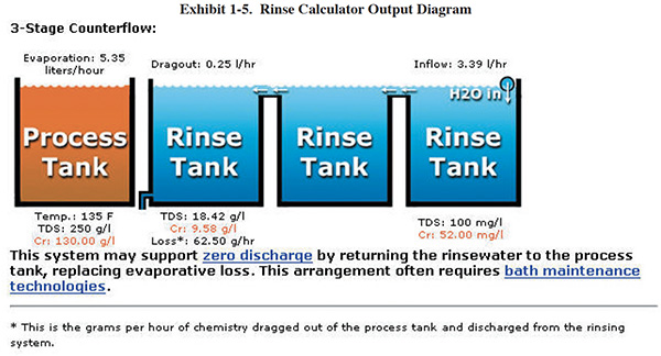
A methodology for measuring dragout rates and rinse water quality can be found in Section 3.5.3. Once you have generated your own TDS data, you can use an on-line calculator to evaluate your rinse system and potential alternative configurations. The online tool is located at (www.sterc.org/subs/rinsecal.cfm). To use the tool, enter the process tank information and other parameters, and then select a type of rinse system. A diagram of the selected rinse system is then displayed. As an example, see the form and diagram in Exhibits 1-4 and 1-5, respectively.
1.2.5 Rinse Controller Update
Conductivity controllers. Conductivity controllers have been in use by the metal finishing industry for more than 25 years. A control system consists of three components:
- a transformer box that houses the solid state circuitry that controls the system; and
- a solenoid valve that opens and closes in response to signals from the circuitry.
Conductivity controllers work by responding to the actual conditions in the rinse tank. When dragout is introduced to the rinse tank, the probe senses a rise in conductivity. When the conductivity level rises above a set-point, the signal from the probe causes the circuitry to open the solenoid water valve. The value remains open until the probe senses a drop in conductivity below another set-point. Both of the set-points are operator-adjustable, to permit use over a range of desired water qualities.
Two types of conductivity sensors are available, conventional and electrodeless.
Conventional conductivity sensors consist of two electrodes that contact the water with a low-level electrical potential between them. The electrodes are sized and spaced to provide a known cell constant, which corresponds to a specific operating range that must match the conductivity range of the rinse water. Since the electrodes in a conventional sensor attract charged particles, they eventually become encrusted or fouled, causing the unit to malfunction. To ensure accurate conductivity measurements, sensors must be cleaned as frequently as every two weeks, and calibration checks must be performed monthly.
Electrodeless sensors, also referred to as inductive-type, eliminate the fouling problems associated with conventional units. The electrodeless sensor consists of two toroids, or wire loops, sealed within a nonconductive casing. The toroids use magnetic fields to interact with the rinse water without contacting it directly.
- The first toroid creates a magnetic field that induces an electrical current in the water. The amount of current induced is proportional to the conductivity of the solution
- The current in the rinse water gives rise to its own magnetic field, which in turn induces a current in the second toroid. Thus the magnitude of the current in the second toroid is proportional to the conductivity of the rinse water.
Electrodeless sensors are easier to operate and maintain because they require less frequent cleaning (since the sensors do not directly attract ions, fouling is unlikely). An additional attribute of electrodeless sensors is their wide conductivity range as compared to conventional units.
Since the publication of the Bluebook (1994), there have been at least two good demonstrations projects that involved
installation and monitoring of conductivity controllers.10,11 Information
from those demonstrations is discussed here.
10Waste Management and Research Center. Pollution Prevention Case Study:
Conductivity Control System Technology, March 2000.
11(Merit Partnership. Reducing Rinse Water Use with Conductivity Control
Systems, December 1996. [The Merit Partnership is a joint venture between U.S. Environmental Protection
Agency (EPA) Region 9, state and local regulatory agencies, private sector industries, and community
representatives. The partnership was created to promote pollution prevention (P2), identify P2 technology
needs, and accelerate P2 technology transfer within various industries in southern California.]
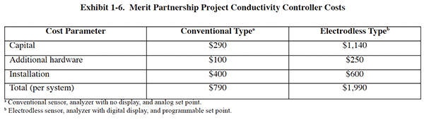
Merit Partnership. The Merit Partnership project involved the installation and monitoring of both conventional conductivity and electrodless controllers. A total of nine units were installed, three each from three different manufacturers. Six of the units were electrodless and three were conventional. The units were installed on rinses following acid activation, copper cyanide plating, nickel plating and decorative chrome plating. Eight of the nine units were wired to a common control panel, where operators could read conductivity measurements and adjust set-points. The other unit was mounted on a wall near the associated rinse tank.
Costs for the conductivity control units, including installation are shown in Exhibit 1-6.
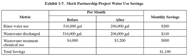
The Merit Partnership demonstration was conducted over a three month time period. The water use and cost saving realized during the project are summarized in Exhibit 1-7. The study results indicate that the majority of savings are derived from reduced use of wastewater treatment chemicals. The study results noted that no adverse effects on product quality were observed during the demonstration.
Waste Management and Research Center. The Waste Management and Research Center (Champaign, IL) installed and monitored two electrodless (inductive loop-type) conductivity controllers at a plating shop that sought assistance in reducing their water use. The controllers were initially set at 1,000 µS and increased in 400 µS increments twice a week. This allowed the system to stabilize and gave production workers time to verify that there were no quality problems as a result of the increase in TDS. The final conductivity set point was 3,600 µS. Over time, no product quality problems were observed and the facility achieved an average water savings of 87.5% per rinse system and an annual water use reduction of 2,808,000 gal ($10,883 saved annually on water and sewer costs). The cost of the controllers was $1,370 each. Additional material and installation costs brought the installed cost to about $2,000 for each unit.
Timer Controls. Timer rinse controls consist of a push-button switch, a timer mechanism, and a solenoid valve. These units operate in a manner similar to conductivity controllers. However, instead of regulating rinse water flow on the basis of rinse tank water quality, the timer controls simply turn water on and off based on a preset time period.
In operation, a finisher lowers parts into the rinse tank and pushes a button (alternatively, a signal could be sent automatically by a momentary switch that is activated whenever a rack or barrel is lowered). The button or switch activates a timer and opens the solenoid valve for a preset time period. After that time period has expired the solenoid valve automatically closes.
The timer setting is selected through trial and error. It is best to select a time period that provides consistently clean rinse water, without excessive waste. Water quality can be periodically monitored using an inexpensive TDS tester, as discussed above. Once set, the time period is not changed unless the general trend of production changes.
The capital cost of timer rinse controls is similar to the price of conventional conductivity controllers. However, these units require less maintenance and generally have a longer lifespan.
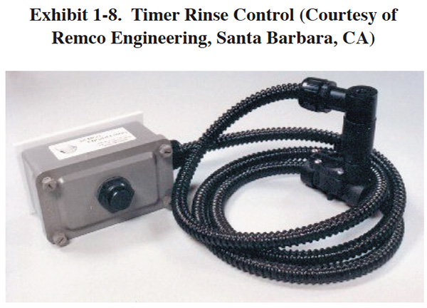
Timer controls continue to be an underutilized technology, in part because there are few commercial units on the market. One currently available unit is shown in Exhibit 1-8. The timer mechanism is built into a NEMA 6 water-proof epoxy box with an external raised pushbutton that energizes the timer. The timers consist of a complete unit with continuous adjustment from 6 seconds to 10 minutes. An alternative range is from 1 minute to 100 minutes.
1.3 ALKALINE CLEANING
1.3.1 Overview
As recently as 1994 (the baseline year for the Strategic Goals Program), metal finishers often used halogenated solvents to remove oils and other contaminants from work pieces prior to plating. But over the next few years, the industry largely abandoned solvent cleaning, except for a few specific applications.
The handwriting was already on the wall in 1994. The Montreal Protocol (an international
agreement limiting the use of substances that destroy the Earth's protective stratospheric ozone layer) required
participating nations, including the U.S., to phase out most of the halogenated solvents then in use, including the
widely used trichloroethane (TCA). In addition a National Emission Standard for Hazardous Air
Pollutants (NESHAP12), covering vapor degreasing and immersion (cold)
cleaning, was enacted that year. Companies operating existing equipment had until December 1997 to comply with the
requirements.
12(The NESHAP was revised in May 2007.)
Much of the cleaning that previously had been done with solvent is now accomplished using alkaline cleaning, the subject of this section. Because it avoids the air emissions and hazardous waste problems associated with solvents, alkaline cleaning can be considered a pollution prevention technology.
Of the solvent cleaning that remains in use today, most is carried out by the aerospace industry, by military depots, by facilities whose applications require precision cleaning operations, and (to a lesser extent) by some facilities involved in general finishing. Even these applications have undergone some changes: most of these facilities use new solvents that have been designed for environmental compliance. The cleaning/degreasing equipment has also changed significantly. It is often downsized, and is generally much more efficient and less polluting (for example, being operated as totally enclosed systems, or being equipped with carbon adsorption capture devices).
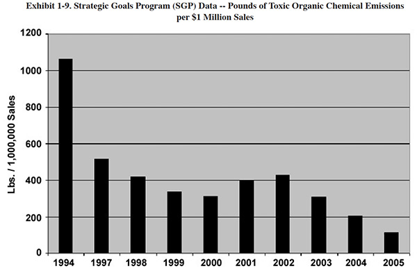
Once the 1994 NESHAP was in place, there was an immediate and major reduction in use of solvent cleaning over the
next three years, followed by a less dramatic, but still steady decline. Exhibit 1-9 shows data from the Metal
Finishing Strategic Goals Program. These values are for quantities of solvent released to the air on a sales
normalized basis.13
13(The SGP started collecting data in 1997, although most companies also
submitted data for 1994, which served as a baseline. SGP data were collected by the STERC as recently as
2008, however there are insufficient data to look reliably past 2005.)
With the declining use of solvent cleaning, alkaline cleaning is now typically the initial operation performed on the plating line. Typically, the process is carried out in two stages using (1) a soak clean followed by (2) an electroclean and rinse. The cleaning stage is important, both for the quality of the finished product and for the overall environmental impact of the plating operation. If cleaning is not properly performed, the result is sure to be
- an increase in rejects (and consequent rework), and
- contamination of process solutions,
two very significant factors that increase waste generation.
Although alkaline cleaning can help prevent pollution, the cleaning baths and associated rinses can themselves be significant sources of pollution. Cleaning baths are the most frequently discarded process solutions on most finishing lines. Spent cleaners and rinse waters, typically treated on site, generate significant quantities of sludge. In addition, certain components of cleaners interfere with the precipitation of metals and can affect compliance with discharge regulations.
Exhibit 1-10 summarizes the pollution prevention and control recommendations for alkaline cleaning. The focus is on improved rinsing methods, bath maintenance, and strategies for on-site treatment. The remainder of this subsection provides supporting information for the recommended strategies, including new technology information not found in the original Bluebook.
1.3.2 DRAGOUT & WATER USE REDUCTION
Excessive dragout is costly because:
- it increases water use
- it results in the need for frequent additions of cleaner
- it increases wastewater treatment costs
1.3.2.1 Dragout
As with any metal finishing process, it is desirable to minimize dragout rates from cleaning tanks to the greatest possible extent. Consider implementing the following process changes, which can be effective methods for reducing dragout from cleaners:
- Modify rack or barrel design to improve drainage
- Improve part orientation to minimize solution carryover
- Operate cleaner bath at a higher temperature to reduce viscosity
- Increase dwell times over tank
- Rotate barrels over process tank
- Use spray rinsing as parts emerge from the cleaner
1.3.2.2 Rinsing
Counterflow rinsing provides the cleanest parts with the lowest water use. In counterflow rinsing, the rinse process is carried out in several stages. Clean water is introduced at the final stage, so the last water that the work piece contacts is the cleanest available. Water from the final rinse then moves upstream for use in the next-to-last stage, and so on.
It is generally advantageous to use a counterflow rinse following alkaline cleaning. A two-stage configuration is typically adequate, although a three-stage system can provide even greater reductions in water use. The rinse system should include some kind of automatic monitoring or control (such as a conductivity monitor or a timer) to ensure that operator inattention does not result in excess clean water consumption.
Benchmarking study participants reported several other successful rinsing practices, including:
- Recovery rinsing. (See Section 3.4.2.3) Recovery rinsing is applicable to alkaline cleaning (although seldom used for this purpose), especially where bath maintenance (e.g., microfiltration) is practiced. In general, when recovery rinsing is used, softened or deionized water should be used for rinsing. One benchmarking survey participant achieved a closed-loop cleaning operation by using three dragout tanks in a counterflow arrangement and a microfiltration system that processes both the bath and recovery rinse. Closing the loop has an additional advantage. The cleaning solution chemistry includes chelating compounds such as EDTA that can interfere with metals precipitation. By closing the loop, finishers can minimize treatment problems caused by the chelating compounds.
- Reactive rinsing. (See Section 3.5.3.4) During reactive rinsing, the rinse following acid dip is reused in the rinse tank following the alkaline cleaner. The acidic rinse helps to remove the alkaline cleaner film better than plain water. However, some facilities warn that use of reactive rinsing sometimes results in precipitated solids in the rinse water, especially with silicated cleaners.
1.3.3 IMPROVED MATERIAL UTILIZATION
During the benchmarking survey several respondents provided suggestions with regard to material utilization and these are summarized below:
- One company indicated that it reuses two-thirds of its used electrocleaner as makeup for its soak cleaner and, therefore, only uses fresh chemistry in the electrocleaner tank. Electrocleaner baths are more concentrated than soak cleaners due to the need for electrical conductivity. When spent, this company's electrocleaner has a sufficient concentration of components to be reusable as a soak clean. However, some fresh solution must also be added. It should be noted that, as one survey respondent pointed out, some electrocleaners do not work well as soak cleaners due to different chemistries.
- Several survey respondents indicated that they have implemented programs with more frequent bath analyses and
that they analyze and subsequently adjust for individual bath components. One respondent analyzes cleaners once
every 8-hour shift. A different respondent indicated that it has also increased analytical work to include
contaminants such as oil and grease. This company uses these results to trigger bath disposal instead of
routinely disposing of the solution based on a time schedule or amount of surface area processed.
- One survey respondent suggested switching from powdered cleaners to liquid cleaners. Another respondent also recommends the switch because powdered cleaners may not completely dissolve in the bath, causing chemical waste and carryover of chemicals to the treatment system or sewer.
- Several survey respondents have substituted biological cleaners for conventional cleaning baths. This technology uses a specially formulated cleaner chemistry (slightly alkaline pH), which permits the buildup of a microbial population that consumes oil and grease. One respondent indicated that they implemented use a microbial cleaner on one production line and due to the results plan to use it in all similar processes. A discussion of biocleaners is presented later in this section.
- Cyanide is used in the formulation of some alkaline cleaners; however, its use has declined significantly over the past 20 years. Several survey respondents indicated that they had recently eliminated use of cyanide cleaners as a P2 measure. One of these companies indicated they use bead blasters to supplement cleaning and although this is less efficient than their old process, it has eliminated use of cyanide-containing cleaners.
1.3.4 BATH MAINTENANCE TECHNOLOGY UPDATE
Bath maintenance is an important aspect of both P2 and cost management. A well maintained bath improves the performance of the alkaline cleaning operation, which in turn reduces reject and rework, and extends the life of the bath. The result is better parts at lower cost, and less waste.
Maintenance includes chemical monitoring and timely additions of fresh chemicals, as well as the use of various technologies to remove contaminants. Knowing what to look for is an important aspect of monitoring. Most finishers limit the analysis of their alkaline cleaner bath to a single component, such as alkalinity or conductivity. When the alkalinity drops below the recommended operating level, they add cleaner solution. This practice fails to take into account that specific components of the cleaning bath are usually degraded or consumed at different rates. A single test will not provide sufficient information.
Alkaline cleaning solutions are a mixture of chemicals, including surfactants, alkali salts, caustic soda, phosphates, and complexing agents. These baths build up concentrations of oil and solids during use. At some point, the cleaning efficiency of the bath is impaired and the solution is discarded, despite the fact that most of the bath's constituents are still usable. Alkaline cleaner bath maintenance technologies are primarily used to remove these suspended solids and oil. In many cases, heavy-duty cleaners must be replaced once per week.
Oil can be partially removed using an oil separator/skimmer or coalescer. Free oils can be removed by simple skimming. These methods work best with cleaner chemistries that are formulated to "split" oils. However, emulsified oils and colloidal solids are not affected by these devices. One benchmarking survey respondent reported adding a reagent to used cleaners that helps split emulsified oil. The oil layer is subsequently skimmed and the cleaner is returned to service.
Most solids can be removed by settling and/or cartridge filtration. Large solids are removed by simple filtration Colloidal solids and oil can be removed by microfiltration. Several benchmarking survey respondents employ this technology. When implementing microfiltration technology it is sometimes necessary to change cleaning chemistry, since microfiltration works best with non-silicated emulsifying cleaners.
Many commercial microfiltration systems used for this application employ ceramic filter membranes in a cross-flow filtration configuration. These membranes are a relatively new development that permits application of microfiltration to solutions and emulsions that are both heated and corrosive. The ceramic membranes are produced in a range of pore sizes that selectively permit a large percentage of the surfactants to pass through the membrane. Typical pore sizes are from 0.2 μ (microns) to 0.8 μ. Crossflow filtration, as opposed to barrier or "dead-end" filtration, permits the application of this technology to high solids-feed streams. With dead-end filtration, all of the feed solution is forced through filtration media by an applied pressure. With a high solids-feed stream, the pores of a deadend filtration device plug. With crossflow filtration, the fluid to be filtered is pumped across the membrane, parallel to its surface. By maintaining a high velocity across the membrane, the retained material is swept off the membrane surface.
EPA Testing of Microfiltration. Under the EPA Environmental Technology Verification (ETV) program
(www.epa.gov/etv), an alkaline cleaner microfiltration technology was evaluated under actual production conditions.
The verification test evaluated the ability of the Silverback™ Model 900 unit to remove oils and recover the alkaline
cleaning chemistry.14
14(Cushnie, George, Evaluation of Silverback Model 900 Alkaline Cleaner
Recycling Systems, April 4, 2000. (http://www.epa.gov/etv/pubs/06_tp_silverback.pdf).)
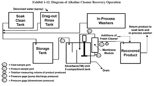
The Silverback™ Model 900 is shown in Exhibit 1-11 and an operational diagram is shown in Exhibit 1-12. The Membralox® Silverback™ Model 900 is an alkaline cleaner recycling system. This unit contains a Membralox® 7P19-40 module made up of seven alpha alumina elements, each with 19 lumens (channels) that are 4.0 mm in diameter. The inside of each channel is lined with an alpha alumina or zirconia membrane having a total surface area of 1.68 m2 (18.1 ft2), and a pore size of 0.2 μ. The manufacturer indicates that the membrane is impervious to nearly all chemicals except for phosphoric and hydrofluoric acids, and can tolerate temperatures up to 200°F.
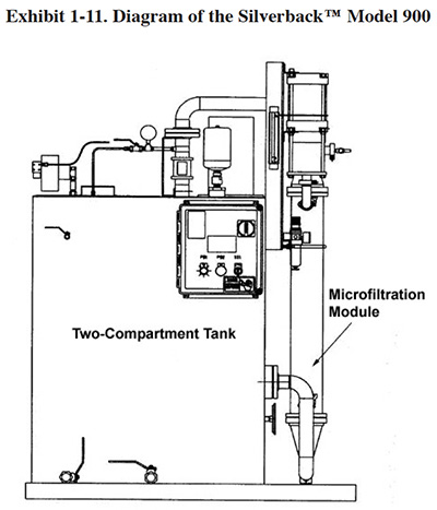
The alkaline cleaner used at the test facility is CLEAN-R-120GR, which is composed primarily of sodium hydroxide, phosphate, glycol ether, octylphenol, and an amine. In use, alkaline cleaner contaminated with oil enters a two-compartment stainless steel tank through a prefilter that removes large particulate material from the feed stream. Free oil accumulates in the initial compartment and can be removed on a periodic basis through a drain port located on the upper part of the tank. The liquid then moves to a second tank compartment through a sub-surface passage, thereby leaving the floating oils in the first compartment. The liquid in the second compartment (referred to as the recirculation tank) is pumped through a microfiltration ceramic filter (0.2 μ). The filter reject returns to the recirculation tank and the recovered alkaline cleaner flows back to the cleaning process. At the demonstration site, the Silverback™ unit recovers 1.0 gpm of alkaline cleaner.
Two test runs of five days each were conducted during the ETV project. Test results show that the unit recovered greater than 95% of the cleaner chemistry, while average contaminant removal was 82% for total suspended solids (TSS) and 90% for oil.
Implementation of the technology reduced the disposal frequency of the alkaline cleaning solution at this facility from 15 times per year to two times per year. The overall volume of concentrated waste generated from alkaline cleaning was reduced by 67.5% and the weight of total solids in the waste products has been reduced by 58.9%.
Operating and maintenance (O&M) labor requirements were monitored during testing. The O&M labor requirement for the equipment was observed to be 3.75 hrs/wk. O&M tasks performed during the verification test include daily inspections of the unit and weekly cleaning of the tank and membrane.
A cost analysis of the Silverback™ Model 900 was performed using current operating costs and historical records from the demonstration site. The installed capital cost (1999) of the unit was $43,000 (includes $36,000 for the unit, $5,000 for storage tanks, and $2,000 for installation costs). The annual cost savings associated with the unit is $32,064. The projected payback period is 1.3 years.
The test results show that the microfiltration technology provides an environmental benefit by extending the bath life of the alkaline cleaner, thereby reducing the amount of liquid and solid wastes produced by the cleaning operation without removing the cleaning constituents of the bath. The economic benefit associated with this technology is low operating and maintenance labor and a payback period of approximately 1.3 years. As with any technology selection, the end user must select appropriate cleaning equipment and chemistry for a process that can meet their associated environmental restrictions, productivity, and cleaning requirement.
Biological Cleaners. A unique approach to bath maintenance that may work for some facilities is biological cleaners, which are an alternative to conventional alkaline cleaners. Typically, these are mild alkaline emulsifying solutions that use biological digestion to remove residual oils from baths that operate at relatively low temperatures. The system is essentially self-regulating, since the microbial activity will adjust itself to the amount of removed oil and grease present in the system. Bio-cleaner systems operate at temperatures between 104°F and 131°F, with a pH range of 8.8 to 9.2, conditions which provide a viable environment for microorganisms. The microbes present in the cleaner system are those normally found in industrial oils and greases.
The cleaning process takes place in two separate operations:
- When parts come in contact with the solution, the oil and impurities are emulsified into micro-particulates
- The micro-particulates are then consumed by microorganisms which are present in the bath
Although the bio-cleaner technology has been has been tested (see results below), it is a relatively new technology and should be approached with prudence. These cleaners introduce a biological process into the shop – a type of process that is otherwise foreign to most finishers. Successful use of this technology requires a different approach to bath operation and maintenance from that used with more common cleaner formulations. If the industry's use of this technology expands, implementation will become easier for each facility as operating experience is communicated through journal publications and reports.
EPA Testing of a Bio-Cleaner. An EPA ETV project evaluated the effectiveness of one particular
bio-cleaner, the BioClean™ system.15 The facility selected for the test was a zinc plating shop.
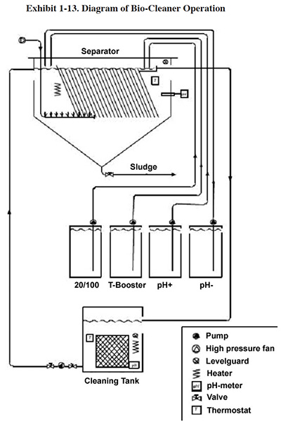
At this facility, the cleaning solutions from four separate cleaning baths are pumped continuously into a holding
tank that feeds the BioClean system (see Exhibit 1-13). After BioClean treatment the cleaning solution is returned,
by gravity, into the holding tank, and is then pumped back into the cleaner tanks. This operation is run in a
continuous mode, with level guards on the cleaner tanks that prevent overfilling.
15(Eskamani, Gus, Environmental Technology Verification Report: Evaluation of
BioCleanUSA, LLC Biological Degreasing System for the Recycling of Alkaline Cleaners ETV
(http://www.epa.gov/etv/pubs/06_vr_bioclean.pdf))
The demonstration project resulted in the following conclusions:
- Implementing the BioClean System reduced the annual amount of alkaline cleaner waste requiring treatment from 34,400 gallons to 6,940 gallons.
- The O&M labor requirement for the equipment was observed to be 2 hrs/wk.
- The installed capital cost (1998) of the unit was$47,569 (includes $27,625 for the BioClean unit, plus $19,944 for installation to four work-centers). The annual cost savings associated with the BioClean System was $86,192. The projected payback period was 0.6 yrs.
1.3.5 TREATMENT OF SPENT CLEANERS
Eventually, as the active ingredients are depleted, all alkaline cleaning solutions need to be discarded. Dumping a cleaner bath directly into a wastewater treatment system will usually upset the treatment process, and may result in a discharge violation for one or more metals. To avoid such problems, consider implementing one of these methods:
- Bleed into General Flow. To implement this option a shop would typically install a holding tank in the waste treatment area that is large enough to hold one or more cleaner tank dumps. Drain valves on the cleaner tanks would be piped to this holding tank. It would be necessary to schedule tank dumps to adequately space out the expected volume of spent cleaner. Once a cleaner dump is transferred to the holding tank, it would be bled at a predetermined rate (e.g., 1%) to the treatment process using a chemical metering pump.
- Pretreatment of Spent Cleaner Before Combining with General Flow. To implement this option, a shop would typically install a batch treatment system, rather than the holding tank discussed in the previous option. A conical bottom tank equipped with a mixer and chemical feed systems is recommended for this purpose. The spent cleaner is chemically treated, solids are removed through a valve in the bottom of the tank, and the treated liquid is metered into the general wastewater flow.
- Hauling Spent Cleaner to a Treatment/Disposal Site. To implement this option, a facility would
transfer spent cleaner from the cleaning tanks to drums suitable for holding or transporting hazardous waste
(e.g., 55-gal. DOT-approved drums). Spent aqueous cleaning solutions may or may not be hazardous, depending its
pH and toxic metal content.16 The drums would be stored on-site and transported by a
licensed transporter to an appropriate treatment or disposal site. If the spent cleaner were determined to be a
hazardous waste, it would be handled in compliance with EPA's hazardous waste manifest system.
16(Federal rules for determining if a waste is hazardous can be found at 40 CFR 261. State rules may supersede federal rules (state hazardous waste rules can be downloaded at: http://www.envcap.org/hwrl).)
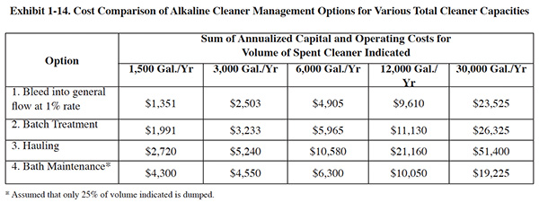
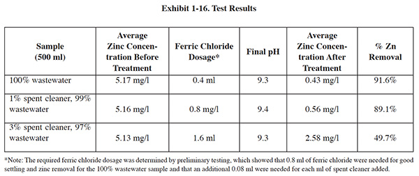
A project was conducted at a zinc plating shop to evaluate and compare these options.17 The
evaluation also included a microfiltration system for bath maintenance. Exhibit 1-14 shows
a cost comparison of the four options for five sizes of cleaning operations, ranging from 1,500 gal./yr. to 30,0000
gal/yr. of spent cleaner generated. For labor calculations it was assumed for options 1, 2 and 3, that cleaning
baths are replaced every two months and that the cleaner is not replaced with option 4.18 The
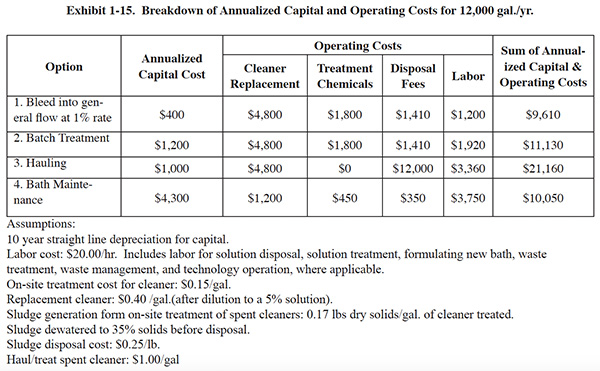
costs shown in Exhibit 1-13 are the sum of annualized capital costs and operating costs. Exhibit 1-15 shows an
example of a breakdown of these costs for one of the five cleaning operation sizes (12,000 gal./yr.).
17(Cushnie George, Chalmer, Paul, Marsh, Greg and Ferguson, David, Management of
Spent Alkaline Cleaners, Plating and Surface Finishing, Nov. 2005
(www.sterc.org/pdf/psf2005/110522.pdf))
18(Therefore, the cleaning tank capacities (could be one or more tanks) for the
five sizes of operations are 250 gal. (1,500/6 = 250), 500 gal., 1,000 gal., 2,000 gal., and 5,000
gal.)
The cost analysis in Exhibit 1-14 shows that for all but the largest cleaning capacity evaluated, bleeding spent cleaner into the wastewater is the most economical option. For the largest capacity, bath maintenance is the more economical option. Although the bleed method is usually less expensive to implement, in many cases, this option is not practical or feasible because wastewater flow is insufficient (and/or too variable) to dilute the spent cleaner to a point where it no longer interferes with the treatment processes. (Based on experimentation, a maximum 1% bleed rate was identified; see Exhibit 1-16). It is also important to keep in mind that intentional dilution is unlawful, so adding clean water to the waste-water flow to achieve a treatable spent cleaner dilution rate is not an option.
Getting back to the cost analysis in Exhibit 1-14, if bleeding spent cleaner at a sufficiently low rate is infeasible,
impractical or just too risky, then either batch treatment or bath maintenance are the most cost effective options.
Batch treatment is more economical with small volumes of spent cleaner. With larger cleaning tank volumes, bath
maintenance becomes more economical: when the generation rate of spent cleaner is between 6,000 and 12,000 gallons,
the replacement costs for cleaner begin to outweigh the annualized cost of bath maintenance equipment. With a 30,000
gal. cleaner capacity, bath maintenance is clearly more economical than batch treatment.19 In
every case analyzed, hauling the spent cleaner was not economical, primarily due to the high labor cost associated
with drumming and managing the waste.
19(This cost analysis does not account for differences in cleaning chemistry
that exist at most facilities (e.g., different cleaners for different alloys, soak clean vs. electroclean,
etc.). However, some facilities have been able to implement bath maintenance by first reducing the number of
different cleaners used. By doing so, they are able to use the same bath maintenance equipment for multiple
cleaning tanks.)
For this analysis, microfiltration was used to establish the costs and benefits of bath maintenance. The underlying assumptions used for cost calculations were based on the previously discussed EPA ETV demonstration project.
Conclusions. Bleeding spent cleaner into the general wastewater flow is risky business, considering the low dilution rate that is required and the normal variability of wastewater flows. At the selected facility, a single cleaner dump has a volume of 1,500 gal. and would require 260,000 gal. of wastewater in order to dilute the spent cleaner to 1%. With an average daily wastewater flow of only 13,000 gpd, it would take 20 days to bleed the spent cleaner into the waste treatment system. Facility management considers such a slow bleed rate to be a non-practical solution and further, because of the risk of non-compliance associated with the bleed method, they have chosen to employ batch treatment. Their decision is corroborated by the results of the cost analysis shown in Exhibit 1-14.
Batch treatment of spent cleaners is an economical alternative for small operations. However, for facilities that use a sufficient volume of cleaner, bath maintenance is a more attractive alternative. The breakeven point appears to occur approximately at 12,000 gal. of spent cleaner generated per year. At this point, the sum of cleaner replacement cost savings and other savings begin to outweigh the annualized capital cost of bath maintenance equipment and other associated costs.
1.4 ACID DIPPING AND PICKLING
Acid pickling refers to processes aimed at removal of scale. (Scale is a surface oxide that is formed when a metal, such as steel, is cooled during the transformation from molten into solid form.) Acid dipping generally refers to processes that remove the alkaline film carried from the previous cleaning step, and that activate the surface of parts prior to plating. The most common acids used for this purpose are sulfuric, hydrochloric, nitric and phosphoric acids. The most significant waste products generated from acid dipping and pickling are:
-
 Spent solutions
- Rinse water
- Wastewater treatment sludge
- Acid fumes
- Scrubber water blow-down
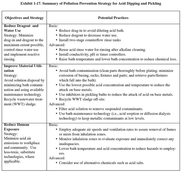
Pollution prevention and control efforts for these processes should be aimed at process changes that reduce pollution and worker hazards, rinsing considerations, bath maintenance/recovery methods, and other waste reduction opportunities. Exhibit 1-17 presents a pollution prevention strategy for acid dipping and pickling.
1.4.1 Water Use Reduction
Excess water introduced by drag-in can dilute acid baths, especially if they are operated at ambient temperatures. Excessive dragout is costly because it results in increased rinse water use, more frequent acid replacement, and increased wastewater treatment costs. To reduce drag-in and dragout, efforts should focus on:
- Rack design
- Part orientation
- Dwell times
Conductivity controls or pH controllers can regulate rinse water use. For final rinses following acid dips, a pH range of pH 5 to 6, or a conductivity of 3,000 to 5,000 µmho, is generally considered acceptable. Timer rinse controls can also be used, with a timer setting adjusted so that it produces similar results.
A two-stage counterflow rinsing configuration following acid dipping or pickling will typically suffice. Some benchmarking survey respondents use reactive rinsing, where the rinse following acid dip is reused in the rinse tank following the alkaline cleaner. The acidic rinse helps to remove the alkaline cleaner better than plain water. However, two survey respondents warned that use of reactive rinsing could result in precipitated solids in the rinse water. One survey respondent employs drag-in/dragout recovery rinsing and reports that it conserves acid.
1.7.2 Bath Maintenance
Bath monitoring and timely additions will improve performance and reduce waste generation. The efficiency of baths can be measured by a weight loss test. Acid baths are commonly contaminated with soils and dissolved metals, both of which reduce performance. Filtration is commonly used for removing particles. Dissolved metals can be removed by acid sorption and diffusion dialysis (see discussion below), although these technologies are generally not cost effective for small operations. Electrowinning can be used for removing copper and zinc from dilute sulfuric baths (10% by volume).
Acid Sorption. Acid sorption is described in the original Bluebook (see Section 5.5), where a
diagram shows how the technology can be applied to an acid dip process. Since the publication of the Bluebook (1994)
the U.S. Department of Defense has investigated use of this technology for their metal finishing depot activities
(e.g., aircraft overhaul).20 The DoD demonstration tests were conducted using a 1-inch diameter
by 12-inch length, packed ion exchange resin column. A set of 10 experimental runs was carried out using
concentrated sulfuric, hydrochloric, nitric, hydrofluoric, and phosphoric acids in combination with a variety of
metals, including iron, nickel, chromium, zinc, and aluminum. The tests represented typical conditions from
pickling, cleaning, activation, anodizing, and stripping procedures. Acid recovery averaged over 80 percent for all
the acids that were tested. The process achieved recovery efficiencies in excess of 95 percent for the acids of
greatest interest, such as hydrochloric, nitric, and sulfuric acids. Metal removal efficiencies were not
reported.
20(Adsorption Treatment Systems to Recover Mineral Acid Solutions)
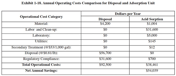
The DoD demonstration offered the following economic analysis, which may be useful to those considering this technology.
The purchase of an acid purification system for the Jacksonville Naval Aviation Depot was compared to off-site disposal of spent acid. A summary of annual operating costs for the two options is shown in Exhibit 1-18. The following assumptions were used:
- Throughput: 175 lb/hr of acid
- Operation: 50 days/yr (400 hrs/yr)
- Acid recovery efficiency: 60-95%
- Average waste density: 15.0 lb/gal
- Labor (burdened): $79/hr
Economic Analysis Summary:
- The total installed cost is $29,153, including adsorption equipment ($19,100), mobile kit ($1,557), multi-tank
manifold ($796), resin ($2,690), and set-up ($5,000).
- Operating costs for an adsorption unit is $38,461 vs. $92,500 for disposal.
- The calculated payback period for investment in the equipment/process: 7 months, using a 15-year analysis, 10% discount rate, and straight line depreciation over 10 years.
- The calculated annual savings is $54,039 in disposal costs.
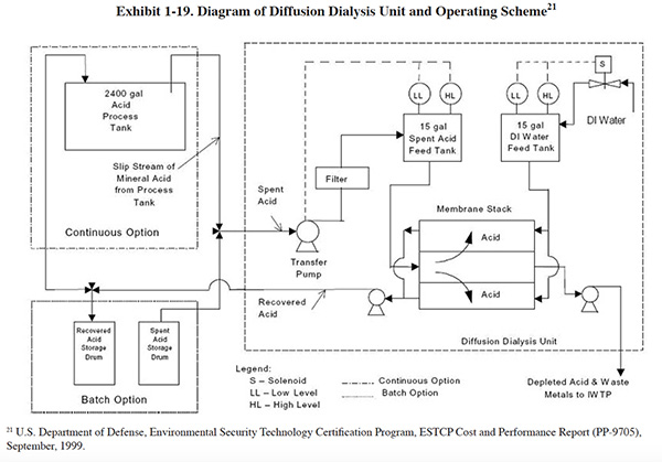
Diffusion Dialysis. Diffusion dialysis is described in the original Bluebook (see Section 5.8). A diagram of an operational system for acid dip bath recovery is shown in Exhibit 1-19. This diagram illustrates the use of both continuous and batch operation. In the continuous mode, acid is withdrawn directly from an acid bath, and the recovered acid stream is returned directly to the bath. The stream containing the contaminants and unrecovered acid is sent to an industrial wastewater treatment system (IWTP). An advantage of operating in the continuous mode is that labor requirements are minimal. Once the operation has been established, the unit runs with only occasional oversight. Another advantage is that continuous processing of the bath acid results in a bath with consistent composition. The primary disadvantage of the continuous mode of operation is that the required processing rate is generally about three times the normal acid disposal rate for the bath, and the waste generation rate is correspondingly larger. In general, continuous operations are only applicable to acid baths with inventories greater than several thousand gallons. At smaller volumes, a batch operation, as shown, is more practical.
In 1999, the Environmental Protection Agency Region I supported research to test a diffusion dialysis acid recovery system. The resulting report documented eight applications of diffusion dialysis at four companies; the results are summarized in Exhibit 1-20.
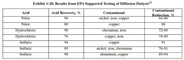
22Bonner, Francis J., and Donatelli, Alfred A., Diffusion Dialysis and Acid Recovery in Metal Operations, The Toxics Use Reduction Institute, University of Massachusetts Lowell, 2001.
The sizing of a dialysis system can be based on the volume of spent acid previously produced; the "rule of
thumb" requires that, at a minimum, the volume of spent acid that was previously discarded should be recycled
once through the dialysis unit over the same period of time it took to generate the spent acid. For example, if a
300-gallon acid bath is being disposed of once per month, then a 10 gallon per day (gpd) diffusion dialysis system
would be recommended. The standard processing rate for diffusion dialysis systems is 0.025 gal/hr/sq ft
(approximately 1 liter/hr/sq meter) of available anion exchange membrane surface area. To obtain the membrane area
needed to process large volumes, the membranes are stacked between gasketed hydraulic flow spacers. These membrane
stacks are usually standardized over a range of differing processing capacities.23
23(Delaney, Sean and Bailey, Daniel, Acid Recycling at Plating for Electronics,
Products Finishing Magazine.)
Comparison of Diffusion Dialysis and Acid Sorption. Diffusion dialysis and acid sorptiont compete directly for acid recovery applications. Based on vendor literature and journal articles it appears that there are approximately equal numbers of diffusion dialysis and acid sorption units in commercial use (about 500 to 750 of each).
Acid sorption is the older of the two technologies, having been first used around 1963. Early applications of acid sorption used available ion exchange resins and equipment. In 1975 a novel ion exchange technique called reciprocating flow ion exchange was applied to acid recovery, which essentially commercialized the acid sorption process. This method of ion exchange is characterized by
- fine particle size resins
- countercurrent elution
- short column heights
- fixed, over-packed resin beds
- short cycles
and a number of other features. The process is ideal for treating small volumes of concentrated solutions with a
minimum of dilution or fluid intermixing in the resin column. Reciprocating flow ion exchange has seen wide
application in the metal finishing industry for the recovery of a wide variety of metals. By employing this method,
the performance of the acid sorption process was significantly improved.24 There is only one
major North American manufacturer of this technology (Eco-Tec, Ontario, Canada).
24(Pajun, Paul and Harrison, J., Anodizing Acid Purification using Resin Sorption
Technology at Pioneer Metal Finishing, AESF Compliance Week, January 1997.)
Diffusion dialysis was developed in the early 1980's in Japan and commercialized around 1990. There are at least three U.S. manufacturers of this technology.
Diffusion dialysis and acid sorption were objectively evaluated by Concurrent Technologies Corporation (Johnstown,
PA) using bench scale equipment to compare their ability to remove metal contaminants and recover free acid from a
contaminated mineral acid bath.25 This comparison was based on one specific application: recovery
of hydrochloric acid (HCl) from iron (Fe) contaminated hydrochloric acid solutions.
25(Kinnel, Wayne A. and Roberts, David S., Mineral Acid Purification
Opportunities, Concurrent Technologies Corp., May 1996.)
For the test, solutions were prepared in a laboratory to closely approximate actual spent hydrochloric acid activation and cleaning baths. The results of testing indicated:
- Diffusion dialysis achieved acid recoveries averaging 97% and iron rejection averaging 86%.
- Acid sorption achieved acid recovery and iron removal efficiencies of approximately 96% and 45%, respectively.
The tests show that for this application, the two technologies achieve almost identical HCl recovery efficiencies; however, diffusion dialysis achieves greater percent rejection of the contaminant metal in the feed and therefore is the more effective technology. It should be noted that for other applications, different results may be obtained.
In terms of capital cost, the two technologies are similar; however, replacement costs for the diffusion dialysis membrane will exceed replacement costs for acid sorption resin over the lifetime of the equipment.
1.4.3 Process Conditions
Higher concentrations of acid and higher operating temperatures dissolve more of the substrate metal. Since dissolved metal will cause the bath to lose effectiveness, lower acid concentrations and lower bath temperatures are preferred from a pollution prevention (P2) standpoint. The less metal that is dissolved into the bath, the longer the life span of the solution. In addition, higher operating temperatures require use of energy, which is also a source of pollution. However, lower is not always better. Lower temperatures and acid concentrations increase the time necessary for pickling and oxide removal, and the finisher must consider the time constraints of the process. There is usually an operating range in which both time constraints and P2 objectives can be met.
1.4.4 Inhibitors
Inhibitors can be added to pickling baths to retard or stop the etching caused by the acid solution, thus providing a P2 benefit. Synthetic inhibitors made up of organic compounds are in common use today with pickling operations. As may be expected, the use of inhibitors increases the time needed to remove scale. When the concentration of inhibitor is increased, less base metal is dissolved and the required processing time increases, especially when low-concentration acids are employed. Yet P2 favors lower acid concentrations. The metal finisher must be prepared to deal with this trade-off.
1.4.5 Chemical Substitution
Mineral acids are effective at removing scale and activating metal surfaces. Because of acid fumes (e.g.,
hydrochloric and nitric acids) and safety concerns, however, substitutes are sometimes sought. Chemical substitution
was implemented by several benchmarking survey respondents, including the use of acid salt substitutes for nitric,
hydrochloric and sulfuric acids. Examples of acid salts used for descaling (pickling) include sodium fluoride,
ammonium persulfate, and ferric sulfate. The acid salts can be mixed with other chemicals to give a more effective
cleaning action. For example, hydrogen peroxide is sometimes added to acid salt solution to improve surface
activation.26
26(Tan, A. C., Tin and Solder Plating in the Semiconductor Industry: A Technical
Guide, Springer Semiconductors, 1993.)
1.4.6 Uses for Spent Baths
Spent acid baths can be used as a wastewater treatment reagent for neutralizing highly alkaline wastes. Spent sulfuric baths containing iron can be used with chromium wastewater as a reducing agent. This practice may result in higher sludge production rates as compared to the use of conventional reagents such as sodium bisulfite.
1.5 ANODIZING
The most common electrolytes used for anodizing are:
- Chromic acid (Type I anodizing)
- Sulfuric acid (Type II anodizing)
- Sulfuric and oxalic acids (Type III anodizing)
The use of chromic acid raises the most significant environmental issues. One of the most important changes in anodizing that has taken place over the past 25 years is a significant reduction in the use of the chromic acid process. This change has occurred primarily because of environmental and health concerns, and the consequent regulations. The most common alternative chosen to replace chromic acid anodizing has been the sulfuric acid process. Chromic acid, however, is still the method of choice for certain applications. One example in particular where chromic acid anodizing remains popular is coating aircraft parts, especially those with recesses (e.g., spot welded assemblies and rolled seams), which trap electrolyte. Lingering sulfuric acid in recesses will cause corrosion and possible part failure. One benefit of the chromic acid process is that residual chromic acid does not appreciably attack aluminum alloys. In addition, the chromic acid process has a less deleterious effect on fatigue life overall than does sulfuric acid anodizing. Nevertheless, aircraft manufacturers continue to seek alternatives to chromic acid. During the past 15 years, the aerospace industry has used a substitute process with a sulfuricboric acid (SBAA) electrolyte to further reduce the use of the chromic acid process.
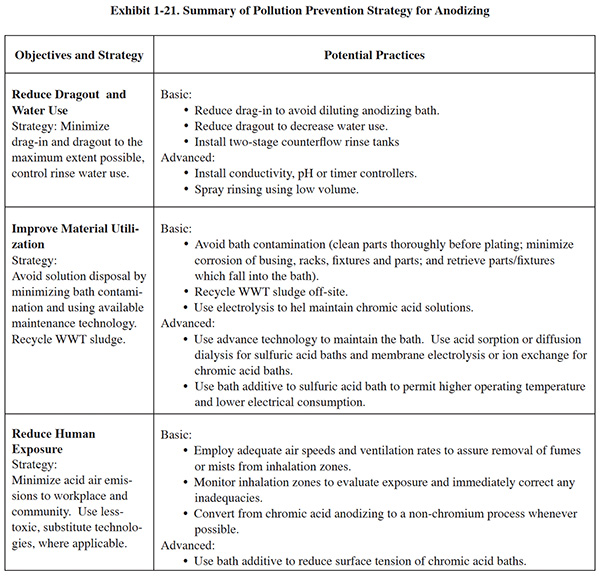
P2 efforts associated with sulfuric acid anodizing have capitalized on opportunities related to rinsing, anode use, bath maintenance, substitution and energy use. Exhibit 1-21 summarizes the following discussion regarding pollution prevention strategies for anodizing.
The anodizing process involves several additional operations, including pretreatment (e.g., etch) and post-treatment (e.g., sealers and dyes). Pollution prevention opportunities also exist for these ancillary processes.
1.5.1 Dragout and Water Use Reduction
A good rinsing configuration for this process is a two-stage counterflow rinsing arrangement. As with all processes, efforts should be directed at reducing dragout, which has a direct bearing on rinse water use. Rinse water control can be accomplished using pH controllers, conductivity controls, or a timer rinse control system. For final rinses following anodizing, a commonly accepted conductivity range is 2,000 to 4,000 µmho.
Some ancillary processes performed in anodizing shops are covered under the Plating and Polishing air pollution
regulation (e.g., nickel acetate and chromate seals).27 For the affected processes (those that
use cadmium, chromium, lead, manganese and/or nickel), shops must implement the required P2 practices; among which
the following are related to dragout control and rinsing:
27(National Emission Standards for Hazardous Air Pollutants: Area Source
Standards for Plating and Polishing Operations; Proposed Rule, Federal Register March 14, 2008 (pp. 14126 –
14151).)
- minimize bath agitation when removing tank objects
- maximize dripping of bath solution back into tank by extending drip time when removing the tank objects and using drain boards (i.e., drip shields)
- optimize the design of barrels, racks, and parts to minimize dragout of bath solution
1.5.2 Sulfuric-Boric Acid Anodizing
The Boeing Company developed and qualified the boric sulfuric acid anodize (SBAA) process in 1990 as a direct
replacement for the chromic acid anodizing28 (CAA) process used on aluminum production pieces.
The SBAA process consists of a sulfuric-boric acid anodizing bath and a dilute chromate sealer bath (about 70 mg/l
chromic acid). SBAA is a commercially available process that provides a protective coating meeting all military and
industrial specifications that apply to the chromic acid anodizing process.
28(Boeing Corporation
(http://www.boeing.com/companyoffices/doingbiz/environmental/chromic.html).)
The SBAA process was tested by the Naval Air Systems Command at NADEP North Island, and has been approved by the
military as an alternative to the chromic acid anodizing process. The SBAA process has since been implemented at
various military depots. Mil-C-8625C (the Mil-Spec that governs all anodized coatings) was revised to include the
SBAA process as an option for aluminum anodizing.29
29(
Joint Services Pollution Prevention and Sustainability Technical Library, Sulfuric/Boric Acid Anodizing,
April, 2003.)
The following are processing characteristic of BSAA as compared to chromic acid anodizing (Boeing):
- Paint adhesion -- As good or better than chromic acid.
- Processing time -- 20 minute process, 30-60%less time than chromic acid.
- Energy Requirements -- Requires lower temperature and voltage, more energy efficient than the chrome-based process.
- Facilities Requirements -- Equipment may require material upgrade.
- Sealing -- Dilute chromate seal must be used. De-ionized water seal is not acceptable BSAA will take longer to reach the same extent of hydration as Chromic Acid Bath Performance.
- Long term bath performance is more reliable
- Licensing -- BSAA requires patent license. No fee if all parts are for Boeing.
- Other -- In dusty environments, addition of sodium benzoate or benzoic acid to BSAA prevents fungus growth.
1.5.3 Cathode Use
Sulfuric acid anodizing can be carried out using either lead or aluminum alloy cathodes. One benchmarking survey
respondent reported substituting aluminum cathode rods for lead cathodes as a P2 measure. In addition to eliminating
lead, the advantage of aluminum cathodes is that they require less current and less cooling, due to the greater
current carrying capacity of aluminum as compared to lead. Aluminum alloy cathodes will also outlast lead cathodes,
which will slowly dissolve unless an electrical charge is maintained on the cathodes when the tank is not in
operation.30
30(Schaedel, Fred C, Try a Holistic Approach to Improve Anodizing Processes,
Products Finishing Magazine, Dec., 2006.)
1.5.4 Process Control
The anodizing process is referenced by more than 75 major aerospace, military and commercial specifications, some of which have overly generous ranges for acceptable chemical concentrations, operating parameters, (e.g., temperature) and impurity levels. Operating the anodizing process within narrow, more desirable parameter ranges will reduce pollution by minimizing rejects and rework, extending the life of baths, and lowering energy use. For example, free sulfuric acid concentration ranges for the various specifications range from 5.0% to 28.4%, although the ideal range is 10 to 11% for Type II and 11.0 to 15.5% for Type III (Schaedel).
Correct use of additives and modifiers can significantly boost efficiency and energy savings. One benchmarking survey participant reduced energy use with Type II anodizing by using a bath additive that allowed the bath to operate at a higher temperature. This reduced the electrical requirements for cooling the anodizing solution. Much of industry operates Type II baths at 70 °F. When a good additive and modifier are used, the bath can be run as high as 85 °F (Schaedel). The same survey respondent indicated that use of a lower-frequency pulse rectifier reduced energy consumption for their hard anodizing process. This same equipment is also applicable to Type II anodizing. Special secondary half-wave rectifiers can also provide an energy savings with Types II and III anodizing (Schaedel).
Bath additives can also extend the life of nickel acetate seals. One such additive adds wetting and dispersing agents
to improve seal quality and prevent smut and white powder formation on parts. It also provides a hydrophobic anodic
coating that helps water to run off parts, thus minimizing spotting.31
31(Merit Partnership, Extending Metal Finishing Bath Life, Dec.
1997.)
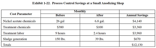
One small anodize shop (23 employees) documented saving of $12,130 per year through improved process solution monitoring and control (Merit Partnership). A breakdown of their cost savings is shown in Exhibit 1-22. In addition to implementing various control measures, their improvements included installing a filter system on the nickel acetate bath.
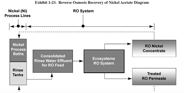
Sealers and Dyes. The Merit Partnership (a joint venture including U.S. EPA Region 9, state and
local regulatory agencies, private-sector industries, and community representatives) successfully demonstrated the
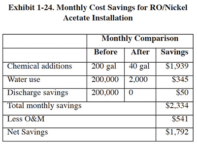
use of reverse osmosis (RO) for recovery of nickel acetate and black dye.32 In each operation (see Exhibit 1-23), the overflow from the
first-stage rinse tank is pressurized by a high-pressure feed pump. Particulates are removed from the feed solution
by two 1-micron cartridge filters. The feed solution then flows in series through spiral wound modules containing
thin-film composite RO membranes (two modules for nickel acetate and four modules for black dye operations). After
separation, a portion of the concentrate stream is returned to the process bath in order to recover process
chemicals. The remaining portion of the concentrate stream is conveyed to the recirculation tank, where it is
temporarily stored before being recirculated through the RO unit. Permeate is conveyed to the second rinse tank and
is reused as rinse water. A small amount of fresh deionized water from an outside source is added to the process
baths in order to make up for evaporative water losses.
32(Merit Partnership, Reverse Osmosis Applications for Metal Finishing
Operations, Jan. 2002 revision.)
The installed cost of the nickel acetate RO unit was $45,000. Annual operations and maintenance costs are $541 (mainly electricity and RO membrane cleaning). Cost savings for this installation are shown in Exhibit 1-24. The payback period for the RO installation was approximately 2 years, not including depreciation of the RO unit (i.e., tax savings).
1.5.5 Special Practices for Chromic Acid
The operation of chromic acid anodizing is affected both by environmental and by safety and health regulations directed toward the control of airborne emissions from the process:
- National Emissions Standards for Hazardous Air Pollutants (NESHAP) (40 CFR. §63.6) for chromium regulates air emissions to the environment.
- OSHA's chromium permissible exposure limit (PEL) regulates the amount of chromium in the air within the shop (29 CFR Parts 1910, 1915, et al.).
P2 practices can help meet these two regulations simultaneously. Chromium is released to the air from anodizing operations during the process, as gases created during electrolysis at the anode and cathode rise through the solution, break at the surface and release an aerosol to the air above the tank. A common P2 practice involves the use of fume suppressants that lower surface tension and/or create a foam blanket that reduces the amount of chromic acid mist released to the air.
 |
 |
There are two basic types of fume suppressants: wetting agents and foam blankets. The difference between foam
blankets and wetting agents is the way in which they reduce emissions:33
33 (Riordan, Barrett J., Karamchandanl, Rohit T. Zitko, Larry J., and Cushnie
George C., Capsule Report Hard Chrome Fume Suppressants and Control Technologies, United States
Environmental Protection Agency Technology Transfer Office of Research and Development, Washington, DC 20460,
EPA/625/R-981002 December 1998.)
- A foam blanket fume suppressant generates a layer of foam across the surface of a solution when current is applied to that solution. The foam layer physically suppresses the mists produced on the surface of plating baths. Foam blankets do not prevent the formation of chromic acid mist – instead, they trap the mist under the blanket.
- Wetting agents lower the surface chemistry of plating baths. This causes gases to escape at the surface of the solution with a diminished "bursting" effect, reducing mist formation.
Another approach to preventing chromium losses to the air is to use tank covers that enclose the top of the anodizing
tank. One commercial unit (Emissions Elimination Device, EED) incorporates membranes that allow gases to pass
freely, while effectively blocking the escape of water vapor and chemical mists (see Exhibit 1-25). Prior to opening
the tank cover, an evacuation system removes chromium-laden air, filters it, and returns the air to the plating room.
Tank covers of this design eliminate the need for fume suppressants and a scrubber system.34,
35
34(Washington, DC 20460, EPA/625/R-981002 December 1998. Graves, Beverly,
Encapsulating Hard-Chrome Plating Tanks, Products Finishing Magazine, Aug., 1999.)
35(Products Finishing Magazine, December, 1997.)
1.5.6 Bath Maintenance
Chromic acid anodizing. Common bath contaminants associated with chromic acid anodizing include:
- Chloride – causes burning or pitting of parts: maintain below 0.3 g/l.
- Sulfate – gives rise to opaque appearance of coating: maintain below 0.5 g/l.
- Trivalent chromium – forms complexes that are ineffective for anodizing: maintain below 4 g/l.
- Aluminum – forms complexes that are ineffective for anodizing: maintain below 3 g/l.
Chloride and sulfate are often introduced via water that is added for evaporative makeup, and for rinsing parts. Using deionized water for these purposes can minimize chloride and sulfate introduction. Precipitation using silver oxide will remove sulfate if it builds up beyond tolerable limits. Limiting the total cathode surface to between one-fifth and one-tenth of the total anode area will minimize the production of trivalent chromium. This can be accomplished by shielding part of the cathode area with wire-reinforced glass plates. When trivalent chromium levels exceed tolerable limits, high current density electrolysis can be used to convert trivalent chromium to the required hexavalent form.
Various technologies have been marketed for removing dissolved aluminum, including ion exchange, ion
transfer (i.e., non-ion-specific membranes including ceramic porous pots and units with
polyfluorocarbon membranes), and membrane electrolysis (i.e., ion-specific membrane). Each
of these technologies is discussed in Section 5. Of these three technologies, only ion exchange is presently a
viable method for removing dissolved aluminum at a rate that prevents buildup of aluminum in the bath. Membrane
electrolysis does an effective job; however only one company produced a suitable unit and, although they are still
servicing existing units, they are no longer selling new equipment.36 Ion transfer has only a
marginal effect on dissolved aluminum concentration and it cannot maintain a chromic acid anodizing bath below
tolerable limits. An EPA Environmental Technology Verification (ETV) test of an ion transfer unit was conducted at a
chromic acid anodizing aerospace facility in 2000.37 The results of the test showed that the
unit does remove some dissolved aluminum from the bath, although the rate of removal was insufficient to prevent the
bath from having to be discarded. During the ten week test, the unit was only able to remove about 25% of the
aluminum that dissolved into solution during the test period.
36 (Personal communication with Dan Vaughan of Ion Sep Corporation, Rockland,
DE.)
37 (Start, Chris, Environmental Technology Verification Report, Evaluation of US Filter
Corporation's RETEC® Model SCP-6 Separated Cell Purification System for Chromic Acid Anodize Bath Solution,
VR-P2MF-10-02, September 2001.)
Although ion exchange is an effective technology for maintaining chromic acid anodizing baths, it generates a significant volume of waste during resin regeneration. The waste stream is typically treated on-site using neutralization and precipitation, which generates a hazardous waste sludge (F019).
Additional information on chromic acid purification can be found in the hard chromium plating section.
Sulfuric Acid Anodizing. Bath maintenance is an important aspect of sulfuric acid anodizing. The anodizing process causes an increase in the concentration of dissolved aluminum. In conventional practice, the bath, or a portion of the bath, is replaced with fresh electrolyte. The spent solution is then typically neutralized and treated using a hydroxide precipitation process, a practice that creates sludge.
A fairly significant number of anodizers have implemented bath maintenance as an alternative to solution dumping. The most widely used technologies for this purpose are acid sorption and diffusion dialysis. Both technologies are discussed in the Acid Dipping process section.
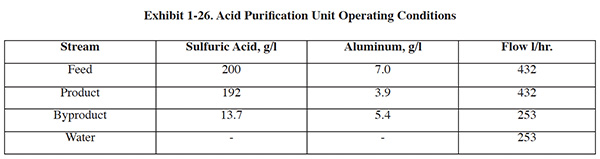
Although they work by very different mechanisms, acid sorption and diffusion dialysis produce approximately the same
results. Exhibit 1-26 shows operating performance data for an acid sorption unit applied to sulfuric acid anodizing
baths.38 For this installation, 96% of all free sulfuric fed to the unit is recovered for reuse.
For every pound of aluminum removed by the unit, 2.5 pounds of sulfuric acid is lost to waste. This translates to a
70% reduction in sulfuric acid purchases and caustic soda neutralization costs when compared to a dump-decant
scenario.
38 (Jan, Paul Pajunen, P.E., Jim Harrison; Anodizing Acid Purification Using
Resin Sorption Technology at Pioneer Metal Finishing, 18th AESF/EPA Conference, 1997.)
A benchmarking survey participant operates a hard coat anodize tank with a maximum aluminum content of 3.75 g/l. When that limit is exceeded, they use the spent hard coat bath as replacement for a sulfuric acid anodize bath, a larger bath that requires a lower acid concentration and has a maximum allowable aluminum concentration of 18 g/l. When the concentrated hard coat bath is used, water is also added to dilute the acid, and the aluminum concentration is proportionally diluted to about 3 g/l. With periodic dumping of the sulfuric acid tank to a treatment system and replacing the sulfuric acid bath with the used hard coat solution, the aluminum sulfuric acid bath never exceeds the 18 g/l limit. The hard coat solution contains additives that are not needed in the sulfuric acid process, but these additives have not caused any operational problems with the sulfuric acid anodizing process. This practice of reusing the hard anodize bath has been in effect for about 15 years.
1.6 CADMIUM PLATING
The number of cadmium plating operations in the U.S. and worldwide has declined significantly during the past 20 years because of the considerable environmental and health concerns associated with cadmium metal. In some parts of the world, such as Europe, cadmium-plated parts cannot be imported or sold. Most cadmium electroplating has been replaced by zinc electroplating. Other popular alternatives include vacuum deposition of aluminum, and zinc and tin alloy plating.
Nevertheless, cadmium provides several distinct advantages over zinc; therefore, its use continues for certain applications. Cadmium:
- provides superior corrosion protection in marine environments
- is less apt to cause hydrogen embrittlement
- has a dense and adherent oxide film that does not form bulky corrosion products
- provides a conductive coating with good lubricity, suitable for fasteners (particularly in aerospace applications)
Seventeen benchmarking survey respondents (12.8%) perform cadmium plating. Two indicated that they are in the process of discontinuing cadmium plating. In an effort to retain customers while eliminating cadmium, one job shop offers to perform R&D for customers to find alternative coatings. Cadmium plating is currently 6.4% of this shop's total metal finishing sales ($9.5 million).
Exhibit 1-27 summarizes the following discussion regarding pollution prevention strategies for cadmium plating.
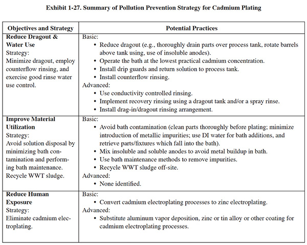
1.6.1 Water Use Reduction
Rinsing following cadmium plating presents challenges to the metal finisher. Due to the relatively low temperature of the cadmium bath, the opportunity to use dragout recovery rinsing is limited. However, some companies from the benchmarking survey do use dragout recovery rinsing or spray rinsing to capture and return dragout to the process tank. A company using spray rinsing is reportedly able to recover all dragout by spraying over a dead rinse and returning that solution. This company, which plates zinc die castings (rack and barrel), has experienced a buildup of zinc in its cadmium plating tank, which is attributed to spray rinsing of the barrels. The zinc contamination problem may force the company to make design changes.
The drag-in/dragout tank arrangement is applicable to cadmium plating. Generally, a good strategy is to focus on dragout minimization and to implement counterflow rinsing and good water use control. Dragout reduction can be achieved by:
- Increasing dwell time
- Rotating racked parts for better drainage
- Redesigning barrels to reduce the volume of trapped solution
Operating the cadmium plating bath at the lowest practical metal level will also lower dragout losses. Water use control can be accomplished by using flow restrictors, conductivity controls, shut-off valves, and timer rinse controls. For final rinses following cadmium plating, a commonly accepted conductivity range is 500 to 700 µmho.
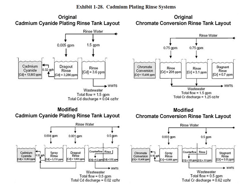
The Merit Partnership investigated ways of improving rinsing efficiency and reducing chemical losses for cadmium
plating at a job shop.39 The original and modified rinse systems for cadmium plating and chromate
conversion coating from their report are shown in Exhibit 1-28. Overall, this system reduced the mass of metal and
wastewater discharged to treatment by about 50%. The calculated payback of the modifications was 1.7 years.
39 (Merit Partnership, Modifying Tank Layouts to Improve Process Efficiency,
Oct. 1996.)
On July 1, 2008 EPA published the National Emission Standards for Hazardous Air Pollutants for Plating and Polishing
Operations.40 This rule impacts many metal finishing operations (EPA estimates 2,900 facilities). It
applies to facilities with plating, polishing or thermal spray processes that contain cadmium, nickel, lead,
manganese and/or chromium. (The rule will not apply to chromium anodizing and electroplating, which are covered
under a previous rule.)
40 (National Emission Standards for Hazardous Air Pollutants: Area Source
Standards for Plating and Polishing Operations; Final Rule, Federal Register July 1, 2008.)
1.6.2 Bath Maintenance
Cadmium baths tend to increase in metal concentration over time, due to the difference between anode and cathode plating efficiency. Some platers compensate for this increase by adding other bath constituents to maintain recommended ratios. This procedure results in significantly higher levels of cadmium in the dragout. An alternative method is to control the cadmium metal concentration in the bath using a combination of insoluble anodes (carburized steel balls) together with soluble anodes. Other accepted bath maintenance methods include filtration and carbonate control (using chilling system).
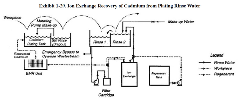
1.6.3 Chemical Recovery
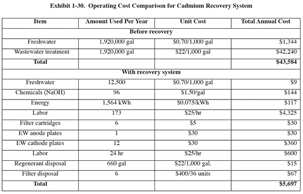
Various chemical recovery technologies have been used with cadmium electroplating. The most frequently used
technologies are electrowinning, ion exchange and evaporative recovery (vacuum type). Electrowinning and ion
exchange applications were demonstrated by EPA on a full scale installation.41 Exhibit 1-29 shows the
cadmium recovery system configuration. Water from the first rinse tank is passed through a filter (8 gpm) to remove
suspended solids that would otherwise clog the resin bed. An anionic resin captures the cadmium-cyanide complex, and
the water is returned to the second rinse. Samples of the rinse water collected before and after reovery were
analyzed. The feed into the exchange unit contained about 2 to 8 mg/l of cadmium, 1 to 35 mg/l of cyanide, and 200
mg/l total dissolved solids (TDS). The flow out of the ion exchange unit was generally below 0.01 mg/l of cadmium and
cyanide, and contained about 150 mg/l TDS. The pH of the rinse water was around 11.5, both before and after ion
exchange. The resin is regenerated, using 15 to 20% sodium hydroxide, when the capacity of the resin bed is reached,
and the regenerant (about 660 gallons per year) is processed in an electrowinning unit. The cadmium metal recovered
by the electrowinning unit (about 70 pounds per year) is reused in the plating tank as anode material. Operating
costs for this installation are shown in Exhibit 1-30. The capital cost of the system was $15,725 and the payback
period for the system was less than one year.
41 (Gavaskar, Arun R.; Olfenbuttel, Robert F.; and Jones, Jody A., Cadmium and
Chromium Recovery from Electroplating Rinsewaters, EPA Risk Reduction Engineering Laboratory,
EPA/600/SR-94/050, April 1994.)
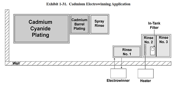
A second demonstration of electrowinning for cadmium was conducted by the Merit Partnership using a high surface area
electrowinning unit (Exhibit 1-31). A heater was installed in the second rinse tank (ideally it would have been
installed in rinse tank 1, but that was a plastic tank) and it was operated at 115 °F. The heater evaporates water,
which concentrates the cadmium, and thereby improves the efficiency of electrowinning. After two months of operation,
the unit had recovered 4.4 pounds of cadmium. The installed cost of the electrowinning system (including heater) was
$9,010. The projected annual savings for the installation was $1,564, mainly due to reduced treatment costs. The
estimated payback
period was 8.7 years.
1.6.4 Non-Cyanide Cadmium Plating
Concerns over occupational health and safety, waste treatment costs, regulatory compliance requirements, and potential liability have encouraged the metal finishing industry to investigate non-cyanide plating technologies. The earliest and most complete cyanide substitution that has taken place in the industry is the conversion from zinc cyanide to zinc chloride or zinc alkaline. Cadmium plating solutions that do not use cyanide are less common, but are commercially available. These include cadmium neutral or acid sulfate and cadmium acid fluoroborate plating solutions. Successful conversion to non-cyanide cadmium plating has been documented.42 At this installation, the facility indicated that many of the anticipated difficulties or perceived shortcomings of a non-cyanide plating electrolyte did not materialize. Reported positive aspects of the non-cyanide bath included:
- The effect of operating temperature was underestimated. Although the temperature never exceeded the maximum
recommended in the operating guide, significant changes in the deposit brightness, uniformity, coverage and
color
(staining) occurred above 80°F. Also, brightener consumption tripled, which led to the installation of a cooling coil. - There are a total of four additives for this process, making it somewhat difficult to interpret Hull cells and make necessary additions.
- The initial cost of equipment for this process can be high, due to the need for zirconium anode baskets.
42 (Products Finishing Staff, Elimination of Cadmium Cyanide Waste Treatment, Products Finishing, Oct. 1997.)
1.6.5 Non-Chromate Conversion Coatings
Chromate conversion coating is a type of post-treatment applied to passivate cadmium and other metal deposits, to
inhibit corrosion, and to promote coating adhesion. The traditional process uses toxic hexavalent chromium
compounds. Recently, the industry has developed less toxic alternatives in order to comply with substance
restriction legislation such as RoHS. One alternative is trivalent chromate conversion, which under testing by the
Navy has shown equal or better effectiveness compared to hexavalent chromium coatings in a 1,000 hour neutral salt
fog test.43 Work by the Navy is continuing and includes evaluation of non-chromium conversion
coatings.
43 (Matzdorf, Craig, Trivalent Chromium-based Post Treatment for Sacrificial
Coatings, AESF/EPA Conference for Environmental and Process Excellence, Feb. 2003.)
1.7 COPPER PLATING
Operating environmentally efficient copper electroplating processes begins with the selection of the plating bath. Twenty years ago, most copper plating was carried out using cyanide baths. However, acid copper baths have become the predominant choice for meeting most metal finishers' needs.
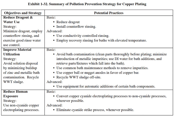
Unfortunately, acid copper baths cannot be used to plate copper directly onto steel or zinc (both of which are commonly plated). In these cases, a copper cyanide strike (thin deposit) can be used, followed by an acid copper solution. This strategy greatly reduces the quantity of cyanide needed. Alternatively, copper pyrophosphate strike solutions are employed by some shops to avoid the cyanide bath when plating steel substrates. In addition, proprietary alkaline, non-cyanide copper plating processes may allow the use of a single solution to replace the two-step copper strike-plate process. However, the use of such solutions is not widespread. Exhibit 1-32 summarizes the following discussion regarding pollution prevention strategies for copper plating.
1.7.1 Water Use Reduction
Minimizing dragout, using multiple rinse tanks, and controlling water use can achieve water use reduction. To reduce dragout, efforts should focus on:
- Rack design
- Part orientation
- Dwell times
To meet rinsing needs and lower water use, a two-stage counterflow rinsing configuration will typically suffice following copper plating.
Although dragout tanks for recovery are typically not employed with copper plating, they can be used with baths operated above 100°F. One benchmarking survey respondent reported using recovery rinsing on copper plating. On continuous production lines, where rinse water needs are relatively stable, flow can be controlled easily by periodically monitoring rinse water conductivity and manually adjusting flow, using a valve. If workflow is sporadic, a conductivity control or timer rinse control should be considered. These devices help to match rinse water use and production flow. For final rinses following copper plating, a commonly accepted conductivity range is 200 to 500 µmho.
1.7.2 Bath Maintenance and Control
Copper electroplating baths are rarely discarded. Common bath maintenance methods include filtration (removes suspended solids), carbon treatment (removes organic contaminants), low current density electrolysis (removes dissolved contaminants), and carbonate freezing or carbonate precipitation (removes excessive carbonate from cyanide baths).
Organic residues from buffing compounds, cleaners, tank and rack materials and other organics can contaminate the bath. Continuously filtering the plating solution through a filter chamber packed with approximately 0.7 grams of activated plating-grade carbon per liter of plating solution (0.1 oz per gallon) will remove small amounts of some organics.
Low concentrations of hexavalent chromium, which can be dragged into the bath on the racks, will produce dull and spotty deposits. Chromium can be reduced quickly to its trivalent form and precipitated by the addition of proprietary reducing agents directly to the plating bath. Hexavalent chromium also can be converted to the inactive trivalent state by using high-current-density electrolysis, or by adding sodium hydrosulfite or sodium stannite. There is disputed evidence that trivalent chromium left in the plating bath can be reoxidized by air back to hexavalent chromium. The best procedure is to precipitate the chromium and remove it by filtering.
Zinc contaminants will plate out simultaneously with the copper, causing brittle and brassy looking deposits. Zinc can be removed by dummying the bath at 0.2–0.4 A/sq dm. Dummying also removes many other metallic contaminants.
Alkaline cyanide solutions are relatively more difficult to control than acid sulfate solutions. Cyanide also involves special handling and treatment procedures because of its acute health hazards and waste disposal requirements. Recommendations for solution control include:44
- Use high-purity, oxide-free anodes for high-efficiency decorative copper plating. Lower quality anodes can be used in strike and medium-efficiency Rochelle-salt cyanide-copper plating baths.
- Use copper balls or nuggets in steel baskets, or slab anodes. Intermingle plain steel anodes with the copper anodes to control the buildup of copper in the bath.
- Bag the anodes (PP, nylon) in order to contain insoluble particles coming from the anodes.
- Keep the anode/cathode ratio between 1:1 and 2:1.
44 (Snyder, Dondald L., Choosing and Troubleshooting Your Copper Electroplating Process, Products Finishing Magazine.)
Acid copper sulfate baths are easier to maintain:
- Use quantitative analysis to control copper, sulfuric acid and chloride.
- Add proprietary addition agents, which control brightness, ductility, and leveling, on the basis of amp-hr. Also regulate their addition by using Hull cells and a copper analysis.
1.7.3 Material Usage
Converting from copper bar anodes to baskets of copper nugget or ball anodes can improve plating efficiency and
material usage rates. Because the copper surface is maintained when nuggets or balls are used, consistently high
plating speeds can be maintained. Bars typically cost about 10% more than nuggets, and not all of the bar material
is consumed in the plating process. Although the work may be distributed evenly, the plating process does not
deplete the copper evenly along the length of the rod. There is typically less erosion in the vicinity of the hook
than at the opposite end. In time, this produces a spear shape that needs replacing. Typically, bars are replaced
when about 15% of the copper material remains. Bars also hang from hooks in such a way that not all of the copper
material is fully immersed in the plating bath. Inevitably, there will be unused material at the top. In basket
operations, copper material is fully submerged, and all of the material is consumed. As the copper dissolves, the
baskets are replenished, leaving no scrap material. Selling the unused bar material back to a copper distributor as
scrap recovers some of the value of the original metal, but the unused copper still represents a sizable cost. A
typical scrap return of $2.00 per lb still produces a scrap cost of $1.00 per lb, not taking into account the costs
related to handling and transportation.45
45 (Panagiotakis, Gregory, The Case for
Anode Baskets, Products Finishing Magazine, Nov. 1995.)
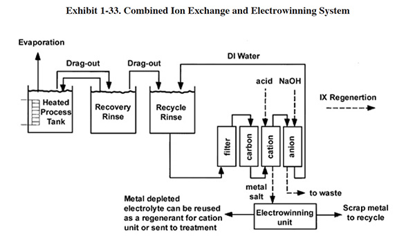
1.7.4 Chemical Recovery
Various chemical recovery technologies have been used with copper electroplating. The most frequently used technologies are ion exchange, electrowinning, and evaporative recovery. The most common approach to copper recovery is a combined system using both ion exchange and electrowinning.
An efficient IX/EW configuration is shown in Exhibit 1-33. A dragout rinse is used to recover the bulk of the copper and therefore allows for installation of smaller and less expensive IX and EW recovery equipment. The ion exchange unit, which is best applied to dilute rinse waters, maintains a low metal concentration in the final rinse. The ion exchange unit concentrates the metal into a regenerant stream, and the electrowinning unit removes the metal.
1.8 DECORATIVE CHROMIUM PLATING
Although some of the same strategies used for hard chromium plating are applied to decorative chromium plating, several key factors have caused companies to take some approaches that are specific to decorative chrome. These factors include:
- Lower plating bath temperature (<125°F)
- Higher average dragout rates
- Widespread use of a substitute plating solution (trivalent chromium).
The advantages to using the trivalent solution include the following:
- Trivalent chromium baths reduce human exposure to toxic hexavalent chromium compounds.
- During operation, the trivalent bath does not generate mist, as the hexavalent bath does.
- Trivalent baths also have a significantly lower chromium concentration and lower viscosity, both of which reduce the quantity of chromium lost due to dragout.
Some benchmarking survey respondents have successfully implemented trivalent chromium plating. But decorative chromium also presents some environmental challenges. For example, the lower bath temperature and higher dragout rate make implementing closed-loop rinsing more difficult than with hexavalent chromium plating. Exhibit 1-34 summarizes the following discussion regarding pollution prevention strategies for decorative chromium plating.
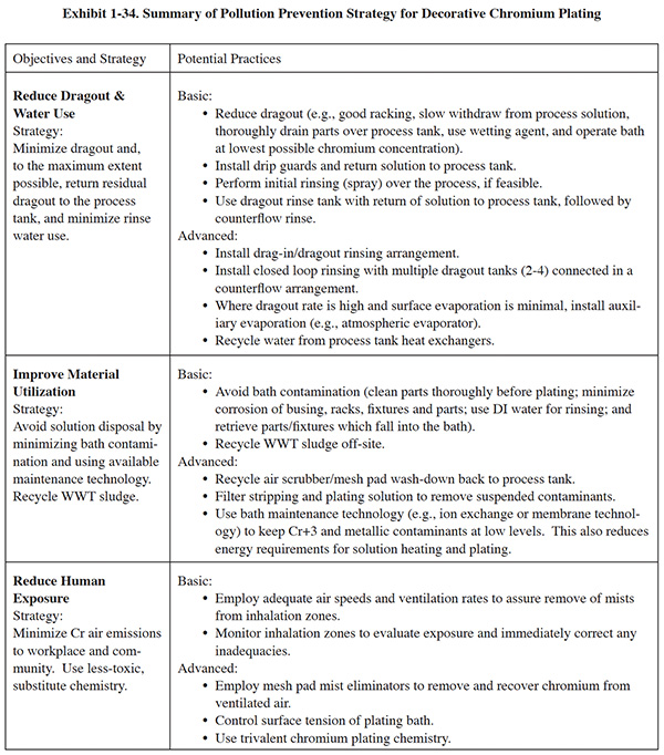
1.8.1 Water Use Reduction
A good formula for environmental success with decorative chromium plating includes dragout minimization, direct recovery, and counterflow rinsing with good water use control. Dragout can be minimized by orienting parts on racks such that they drain completely, slowly withdrawing parts from the process solution, suspending the parts over the process tank for drainage (see draining/rinsing over the plating tank), and using a dragout recovery rinse followed by a multiple-stage counterflow rinse.
Another approach to dragout minimization is to operate the bath at a lower, but still acceptable, chromium concentration. A number of survey respondents have implemented most or all of these P2 elements.
Water use control is often achieved simply with flow restrictors due to the continuous nature of workloads. However, for decorative chromium lines that are not operated continuously, additional controls are needed, such as conductivity controls or timer rinse controls. For final rinses following decorative chromium plating, a commonly accepted conductivity range is 100 to 300 µmho. Due to the lower bath temperature and higher dragout rates, most companies do not achieve closed loop rinsing (although two exceptions were identified by the benchmarking survey). As a result, companies frequently install recovery equipment, the most successful of which is the atmospheric evaporator.
One company that has closed-loop rinsing uses a drag-in tank and three final rinses following plating. The tanks are organized in a counterflow arrangement. This company also has a separate "holding tank." Deionized water is fed to the last rinse and counterflows to the first rinse. The solution in the first rinse flows to a holding tank. The plating solution is circulated continuously to the holding tank. The holding tank provides flow equalization by balancing the incoming water flow rate and the evaporation rate in the plating tank. Bath maintenance (porous pot) is also performed in the holding tank, which saves plating tank space. The drag-in solution is circulated to the first rinse tank. A "bubble pump" (no moving parts) is used to circulate the drag-in tank solution (at 3.5 gpm). This arrangement is referred to as a drag-in/dragout recovery rinsing scheme. It contributes to closing the loop on rinsing.
Survey respondents listed additional P2 methods that relate to rinsing. These include using wetting agents to reduce viscosity, and spray rinsing parts over the process tank.
1.8.2 Bath Maintenance
Returning dragout to the process tank may result in a buildup of contaminants in the plating bath. This buildup is a concern especially with zero wastewater operations. Contaminants, contributed from various sources, can lead to slower plating rates and poor deposits. The first line of defense against contaminant buildup is prevention. Examples of good practices include:
- Thoroughly cleaning parts before plating
- Minimizing corrosion of busing, racks, fixtures and parts
- Using deionized water for rinsing
- Avoiding drag-in of sulfate and chlorides
- Avoiding exclusively plating inner diameters
- Retrieving parts or fixtures that fall into the bath.
To deal with contaminant buildup, which occurs even when prevention measures are taken, companies can install bath maintenance technologies. Methods used include filtering, porous pots, and more advanced technologies such as membrane electrolysis and ion exchange. Of the available technologies, ion exchange is the most effective and reliable. However, ion exchange creates a significant waste stream as a result of resin regeneration. This stream is typically treated on-site using neutralization and precipitation, and results in the formation of hazardous sludge (i.e., F006). Therefore, the value of preventing bath contamination cannot be overemphasized.
Use of ion exchange for removing metal impurities is particularly well-established for hexavalent chromium plating
baths. In these situations, cationic impurities (e.g., iron, copper, and nickel) are being separated from the
desired anionic plating species (i.e., hexavalent chromium). This can be accomplished using a strong acid cationic
resin. Ion exchange purification using a trivalent chromium bath is a more significant challenge because both the
metal contaminants and the desired bath species are cationic. Trivalent baths are sensitive even to low
concentrations of metal contaminants, including copper, zinc, and nickel (copper and zinc have been reported to
cause discoloration and poor coverage at concentrations as low as 20 mg/l).46 For trivalent chromium
baths, purification can be achieved by using a chelating ion-exchange resin having a very high affinity for the
cationic metal ion contaminants compared to the affinity for trivalent chromium. Commercial systems for this
application that operate on a continuous basis (i.e., the plating bath is not taken out of operation) are
available.
46 (Woodle, Roger and Hosea, J. Michael, Ion Exchange for Trivalent Chromium
Plating Baths, Products Finishing Magazine, Nov. 1997.)
1.8.3 Air Quality
Decorative hexavalent chromium plating causes the evolution of chromic acid mist. The quantity of misting is generally much less than with hard chromium plating. Fume suppressants can be used to lower the surface tension of the bath and thereby reduce the generation of fumes. One benchmarking survey respondent suggested that maintaining the surface tension below 45 dynes/cm greatly reduces the amount of mist being generated and reduces dragout.
Well-designed and operated ventilation systems prevent the chromium fumes from entering the workplace. In turn, the ventilated air is processed by scrubbers and/or mist eliminators to prevent emissions of chromic acid to the atmosphere.
Additional information on air quality issues for chromic acid baths is found in the chromic acid anodizing section.
1.9 ELECTROLESS NICKEL PLATING
Compared with solutions used with electroplating processes, electroless nickel (EN) plating baths have a very limited life span. Because these baths are discarded regularly, electroless nickel plating generates a significant quantity of waste.
Exhibit 1-35 summarizes the following discussion regarding pollution prevention strategies for electroless nickel plating.
1.9.1 Bath Maintenance
Operating environmentally efficient electroless nickel plating processes begins with efforts to maintain the bath in a usable condition for an extended time. Minimizing outside contamination and maintaining the bath's constituents at proper concentrations can help.
In addition, technology is available to regenerate baths and keep them operating for an extended time. The overall electroless nickel deposition reaction can be generally written as:
3NaH2PO2 + 3H2O + NiSO4 = 3NaH2PO3 + H2SO4 + 2H2 + Ni0.
Sodium hypophosphite (NaH2PO2) reduces nickel sulfate to metallic nickel, and is oxidized to sodium orthophosphite (NaH2PO3). As the deposition of nickel proceeds, the orthophosphite concentration increases. Nickel salts and other constituents are added to the bath to make up for the chemicals consumed by the plating process. However, the process cannot continue indefinitely because of the buildup of by-products.
The quality of the nickel deposit diminishes over time and the nickel bath must usually be discarded after 7 to 12 metal turnovers (MTO). (One turnover is said to occur when the cumulative amount of nickel added is equivalent to the original quantity in the bath.) The deterioration of the bath is caused mainly by an excessive buildup of orthophosphite.
In recent years, electrodialysis (ED) has become a popular method to extend the life of electroless nickel baths.
Originally, the ED process was used on a batch basis to rejuvenate the EN bath after it was partially contaminated,
or after it had completely reached the end of its useful life.47 Batch treatment, although relatively
successful, had the drawbacks of having to remove the solution from production, and resulting in a
"jig-saw" curve of bath contaminants, which leads to unpredictable performance results. Continuous
processing was not originally used because of technical hurdles, including lack of available membranes that could
tolerate the operating temperature of the EN bath. New developments have apparently overcome the technical issues.
One promising approach is use of monopermselective ion exchange membranes and a modified arrangement of anionic and
cationic ion exchange membranes in a system referred to as Electro-Dialysis of Electroless Nickel
(EDEN).48
47 (The Merit Partnership, Extending Electroless Nickel Bath Life Using
Electrodialysis, U.S. EPA Region 9, July 1998.)
48 Longfield, Peter and Orgill, Graham, The EDEN System for Electroless Nickel Bath Life Extension
and Consistent Quality, AESF SUR/FIN 2005 Proceedings.)
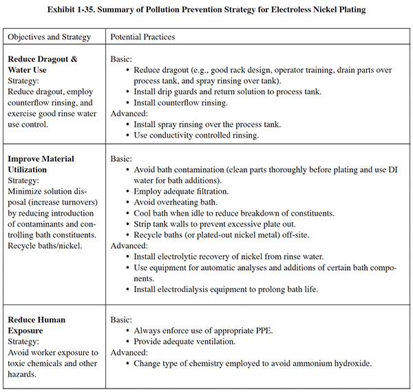
A flow diagram of continuously regenerated EN using the EDEN approach is shown in Exhibit 1-35. The electrodialysis stack is supplied with high volume pumps from two reservoir tanks for the diluate and the concentrate, respectively. The diluate tank is continuously supplied with a low volume flow of approximately 10 gph (37.5 l/hr) from the electroless nickel-plating tank. The diluate is cooled by a counterflow heat exchanger to limit the solution temperature in the stack to maximum 104°F (40°C). The current density supplied to the electrodialysis stack is controlled by a specific gravity sensor in the diluate reservoir, and therefore adjusts the stack performance to the actual plating bath loading or operating time. The second solution circuit of the concentrate comprises an automatic pH-control and automatic water dosing to keep the concentrations of sodium, sulfate and orthophosphite in the optimum range. The typical bleed stream is approximately 4 gph (15 l/h). The regeneration unit also contains an automatic controller for the nickel content in the plating bath (photometric analysis of Ni) and the pH value to allow for fully automated addition of the replenishment chemicals to the electroless plating bath (Longfield).
Under production conditions, the EDEN system has proven to have a bath life of 2,150 MTO.
1.9.2 Disposal of Spent Baths
When baths deteriorate and require disposal, companies may process them on-site to recover the nickel (plating the metal out onto steel wool), or may send the baths off-site for recycling. Some chemical suppliers offer bath recycling. Recycling avoids treating the spent electroless nickel bath, which is a difficult task due to the presence of complexing agents such as EDTA.
1.9.3 Dragout and Water Use Reduction
Benchmarking survey respondents employ common methods for dragout reduction such as good rack design and good racking practices, operator training, draining parts over the process tank (see draining/rinsing over the plating tank), and water use control methods such as flow restrictors. Rinsing following electroless nickel plating typically consists of two to three counterflow rinses. Some companies use recovery rinsing, but there is concern that it may lead to faster deterioration of the bath. Also, some companies use spray rinsing over the bath.
On July 1, 2008 EPA published the National Emission Standards for Hazardous Air Pollutants for Plating
and Polishing Operations.49 This rule impacts many metal finishing
operations (EPA estimates 2,900 facilities). It applies to facilities with plating, polishing or thermal spray
processes that contain cadmium, nickel, lead, manganese and/or chromium. (The rule will not apply to chromium
anodizing and electroplating, which are covered under a previous rule.)
49 (National Emission Standards for Hazardous Air Pollutants: Area Source
Standards for Plating and Polishing Operations; Final Rule, Federal Register July 1, 2008.)
With this regulation EPA did not establish emission limits for plating and polishing operations as they did with chromium plating, but instead required plating and polishing facilities to implement specific pollution prevention (P2) and control practices that are related to air emissions, dragout and rinsing:
- minimize bath agitation when removing tank objects
- maximize dripping of bath solution back into tank by extending drip time when removing the tank objects and using drain boards (i.e., drip shields)
- optimize the design of barrels, racks, and parts to minimize dragout of bath solution
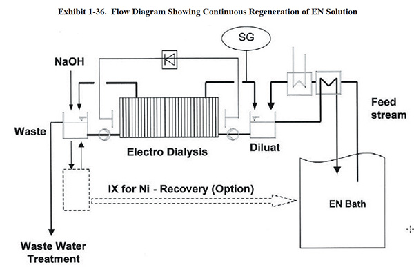
1.9.4 Air Quality
Electroless nickel processes should be ventilated to avoid emissions within the workplace. One survey respondent indicated it uses a scrubber to remove contaminants from the ventilated air stream. Two survey respondents switched from using a plating solution containing ammonium hydroxide for pH control to one with potassium carbonate in order to reduce employee exposure.
1.9.5 RoHS & ELV Compliant Electroless Nickel
Over the past few years, a number of new environmental directives have come out of Europe and Asia, encompassing mainly the automotive and electronics industries. The purpose of these directives is to reduce the amount of toxic materials entering the environment by limiting the amount of certain toxic substances allowed in a manufactured product and providing for the recyclability of the manufactured product. The three major directives affecting the metal finishing industry are:
- End of Life Vehicles (ELV, Directive 2000/53/EC) – Aims to reduce the amount of heavy metals contained in an automobile and provide for the recyclability of automobile components.
- Restriction of the Use of certain Hazardous Substances in Electrical and Electronic Equipment (RoHS, Directive 2002/95/EC) -- Restricts use of hazardous substances in electrical and electronic equipment.
- Waste Electrical and Electronic Equipment (WEEE, Directive 2002/96/EC) -- Imposes the responsibility for the disposal of waste electrical and electronic equipment (WEEE) on the manufacturers of such equipment.
The primary heavy metals addressed in these regulations are cadmium, lead, hexavalent chromium, and mercury. In
electroless nickel plating, cadmium and lead are the major concerns; lead and cadmium are added to electroless
nickel systems for stability and brightness. The ELV and RoHS Directives specify the limits for cadmium and lead in
an electroless nickel deposit to less than 100 and 1,000 ppm, respectively. To meet this challenge, electroless
nickel formulators have developed ELV and RoHS compliant baths. These systems can provide stable, simple-to-use
processes capable of meeting any of the current electroless nickel specifications. The current downside to switching
to these processes is that there will be a learning curve by both platers and suppliers as the new technology
evolves and improves.50
50 (Bellemare, Rich, RoHS and ELV Compliant Electroless Nickel, Products
Finishing Magazine, Oct. 2005.)
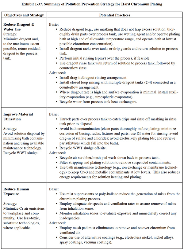
1.10 HARD CHROMIUM PLATING
The key to environmental success with hard chromium plating is direct recovery. The hard chromium bath is operated at an elevated temperature (130 – 140°F). This results in surface evaporation rates of 0.05 to 0.07 gal/hr/ft2. A 48-in. x 96-in. process tank operated at 140°F will evaporate 2.24 gal/hr. or about 54 gal over the course of 24 hours, which provides an opportunity to recover an equal volume of solution. As facilities approach 100% recovery of dragout, they must grapple with the buildup of bath impurities that will inevitably occur. Exhibit 1-37 summarizes the following discussion regarding pollution prevention strategies for hard chromium plating.
1.10.1 Dragout Recovery
Companies can maximize use of this recovery opportunity by returning concentrated solution to the process tank. Solution sources include
- drips from parts exiting the process tank
- solution caught by splash guards or trays
- scrubber water or mesh pad wash-down
- solution from rinsing
Because rinsing can generate a large volume of dilute chromium-bearing water, it is important to use a well-engineered, multiple-tank configuration that concentrates the dragout into the smallest possible volume.
In most cases, a three-stage counterflow rinsing arrangement will generate a sufficiently low flow that the entire volume of rinse water can be returned to the bath. In situations where there is insufficient surface evaporation to achieve zero wastewater discharge, an atmospheric evaporator can be installed to increase the overall evaporation rate.51 Benchmarking survey respondents listed additional P2 methods that relate to rinsing. These include:
- use of drag-in/dragout recovery rinsing
- splash guards on all tanks
- using wetting agents to reduce viscosity
- suspending racks over the process tank to drain
- spray rinsing parts over the process tank
- unracking over the process tank
51 (Mason, Sam, Case Study: Zero Sewer Discharge for a Hard Chrome Plating Facility; 20th AESF/EPA Conference, February, 1999.)
1.10.2 Bath Maintenance
Returning dragout to the process tank may result in a buildup of contaminants in the plating bath. This buildup is of particular concern with zero wastewater operations. Contaminants, contributed from various sources, can lead to slower plating rates, poor deposits and higher energy bills. The initial line of defense against contaminant buildup is prevention. Examples of good practices include:
- Installing a dedicated etch tank for reverse etching
- Thoroughly cleaning parts before plating
- Minimizing corrosion of busing, racks, fixtures and parts
- Using deionized water for rinsing
- Avoiding drag-in of sulfate and chlorides
- Avoiding exclusively plating inner diameters
- Retrieving parts or fixtures that fall into the bath
To deal with contaminant buildup, which occurs to a certain extent even when prevention is employed, companies can install bath maintenance technologies. Solution filtering is an effective method of removing particulate contaminants from the bath; however, it has no effect on dissolved contaminants, such as iron and other tramp metals. Methods used for dissolved metal removal include porous pots, membrane electrolysis, and ion exchange.
Various technologies have been marketed for removal of dissolved tramp metals (e.g., Fe, Cu, Ni), including
ion exchange, ion transfer (i.e., non-ion-specific membranes including ceramic porous pots
and units with polyfluorocarbon membranes), and membrane electrolysis (i.e., ion-specific
membrane). Each of these technologies is discussed in Section 5. Of these three technologies, only ion exchange is
presently a viable method for removing dissolved metals at a rate that prevents a buildup in the plating bath.
Membrane electrolysis does an effective job; however only one company produced a suitable unit and although they are
still servicing existing units, they are no longer selling new equipment.52 Ion transfer has only a
marginal effect on dissolved tramp metals and it cannot maintain a hard chrome plating bath below tolerable limits.
52 (Personal communication with Dan Vaughan of IonSep Corporation, Rockland,
DE.)
Two types of ion transfer units were tested by the Navy on hard chrome baths; an external
ion transfer unit and an in-tank porous pot.53 The external unit is the same technology tested by the EPA
ETV program for purification of chromic acid anodizing solution (see anodizing section). Results of the testing
showed that very little dissolved metals impurities are transferred through these membranes. The actual transport
mechanism is the physical transfer of plating solution (bucketing or bailing) into the catholyte compartment. Once
there, some "precipi-tation" of tramp metals occurs and they are removed as a sludge. Both systems are
effective for conversion of trivalent chromium to hexavalent chromium. However, for this purpose, they are no more
effective than simple "dummy plating," which can be accomplished using materials present in most chrome
shops.
53 (Koff, Jennie and Stencel, Nicholas, Evaluation of Performance Capabilities
& Operational Requirements of Chromium Purification Technologies, Naval Facilities Engineering Service
Center ; 16th AESF/EPA Pollution Prevention and Control Conf. (Feb. 1995).)
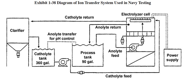
A diagram of the ion transfer system is shown in Exhibit 1-38. Testing was performed by attempting to purify 90 gal. (341 liters) of plating solution (process tank). The initial catholyte solution was made by adding chrome plating solution to tap water until a pH of 1.8 was achieved. During the test, the pH of the catholyte solution increased and it was necessary to transfer 6.6 gal/day (25 l/day) of plating solution from the "process tank" to the catholyte tank in order to maintain a pH of 1.8 to 2.0. This physical transfer of anolyte is the mechanism for moving the dissolved tramp metals into the catholyte tank; electrotransport of metals was "minimal."
Testing of the porous pot showed similar results. The Navy concluded that "The performance of ion transfer systems appears to be quite low for tramp metal removal". Further, the Navy stated that "Relatively high O&M labor requirements were experienced with both ion transfer systems."
Although ion exchange is an effective technology for chromic acid anodizing bath maintenance, it has some limitations and drawbacks:
- IX generates a significant volume of chromium-bearing waste during resin regeneration, which is typically treated on-site using neutralization and precipitation, and results in production of a hazardous waste sludge (F006).
- Since resin is a plastic material, it can degrade if left in contact with a full strength chrome bath for extended periods of time.
- The concentrated nature of the chromic acid limits the exchange capacity that resin has for metals.
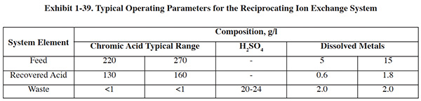
One commercial product for this application that overcomes most of the limitations is a reciprocating flow
ion exchange technology.54 This system includes appropriately
selected ion exchange resin and employs short cycle times that reduce the ion exchange resin/chromic acid contact
time. In operation, a portion of the plating solution is transferred to a feed tank to allow cooling to minimize
oxidative effects. The solution is then pumped through the short column of fine mesh strong acid cation resin at 60%
of its normal bath strength. The resulting purified solution, with up to 90% of the metallic impurities removed in a
single pass, is collected in a product tank for return back to the plating bath. Extra volume created by the
dilution effect is not a problem at most shops, as normal evaporation losses from the chrome bath itself creates a
hydraulic balance (although it could reduce the amount of recovery accomplished by dragout recovery rinsing).
Regeneration is undertaken by using diluted sulfuric acid. Typical process specifications for this technology
(supplied by the manufacturer) are shown in Exhibit 1-39. This same technology is applicable to decorative chromium
plating and chromic acid anodizing.
54 (Pajunen, Paul, and Sheedy, Michael, Metal Removal and Recovery from Process
Solutions Using Short Bed Ion Exchange, SM Technical Paper 181, Eco-Tec Corporation, Nov. 2006.)
Over the past 5 to 10 years there has been a flurry of research activity in the U.S. and abroad aimed at developing a better method of chromium bath purification. Among others, this includes:
- Laboratory investigations of porous pot and membrane electrolysis55
- Laboratory testing of a high pH treatment chemical process56
- Research on a method using a ceramic microfilter57
- Research on modifications to membrane electrolysis using two and three-compartment cells58
- Laboratory testing of a fuel cell cathode ion exchange membrane process59
- Laboratory testing of membrane electrolysis using a sulfuric acid catholyte60
55 (Donepudi, V.S., Khalili, N.R., Kizilel R. and Selman, J.R., Purification of Hard
Chromium Plating Baths-Options and Challenges, Plating and Surface Finishing, April, 2002.)
56 (Benaben, P. and Popakul, J., Purification & Recycling Process For Hexavalent Chromium
Solutions Using a Low-cost Chemical Method, Plating and Surface Finishing; December, 2000.)
57 (Stewart, David, R. Thoen, Paul, and Grove, Tom, In Tank Removal of Hard Chromium Plating
Contaminates, Aerospace/Airline Plating & Metal Finishing Forum, March 2001.)
58 (Kruglikov, Sergey S., Turaev, Dmitri Yu, The Use of Anionic Membranes for the Removal of Cationic
Impurities from Chromium Plating Solutions, SUR/FIN 2004, June 2004.)
59 (Ahmed, M. I., Khalili, N. R., Donepudi, V. S., Smotkin, E. S., Selman, J. R. and Holsen, T.M.,
In-Process Contaminant Removal from Hard Chromium Plating Baths Using a Fuel Cell Electrode Ion-Exchange
Membrane Process, 22nd AESF/EPA Conference; January, 2001.)
60 (Miller, P.O., Taylor, E.J., Zhou, C.D., and Renz, R.P., In-process Purification of Plating Baths,
21st AESF/EPA Conference; January, 2000.)
Although some of this research shows promise, as yet no commercial products have resulted from this work. As such,
there remains a significant opportunity for an effective chrome bath purification technology that can
compete with ion exchange.
1.10.3 Air Quality
The operation of hard chrome plating is affected both by environmental and by safety and health regulations covering airborne emissions from the process:
- National Emissions Standards for Hazardous Air Pollutants (NESHAP) (40 CFR. §63.6) for chromium regulates air emissions to the environment.
- OSHA's chromium permissible exposure limit (PEL) regulates the amount of chromium in the air within the shop (29 CFR Parts 1910, 1915, et al.).
P2 practices can help meet these two regulations simultaneously. Chromium is released to the air from plating operations during the process, as gases created during electrolysis at the anode and cathode rise through the solution, break at the surface, and release an aerosol to the air above the tank. A common P2 practice involves the use of fume suppressants that lower surface tension and/or create a foam blanket that reduces the quantity of chromic acid mist released to the air.
There are two basic types of fume suppressants: wetting agents and foam blankets. The difference between foam blankets and wetting agents is the way in which they reduce emissions:61
- A foam blanket fume suppressant generates a layer of foam across the surface of a solution when current is applied to that solution. The foam layer physically suppresses the mists produced on the surface of plating baths. Foam blankets do not prevent the formation of chromic acid mist – instead, they trap the mist under the blanket.
- Wetting agents lower the surface chemistry of plating baths. This causes gases to escape at the surface of the solution with a diminished "bursting" effect, reducing mist formation.
61 (Riordan, Barrett J., Karamchandanl, Rohit T. Zitko, Larry J., and Cushnie George C., Capsule Report Hard Chrome Fume Suppressants and Control Technologies, United States Environmental Protection Agency Technology Transfer Office of Research and Development, Washington, DC 20460, EPA/625/R-981002 December 1998.)
Another approach to preventing chromium losses to the air is to use tank covers that enclose the top of the anodizing tank. These are discussed in the chromic acid anodizing section.
Mesh pad mist eliminators can be used instead of standard wet scrubber systems to recover chromic acid that is exhausted from the surface of a tank. A well designed system includes an automatic spray wash down device that keeps the mesh pads clean while returning the chromium rinse back to the plating tank. The return of the wash-down solution will compete with recovery rising for available tank space generated by evaporation, and in some cases will require that supplemental evaporation be provided (e.g., installing an atmospheric evaporator, or keeping chrome tanks at operating temperature during idle hours).
1.10.4 Energy Conservation
Electricity is a significant operating cost for hard chrome plating, as shown by the Benchmarking Survey results. Fortunately, a number of P2 methods exist that can significantly reduce these energy costs:
- Keep total metallic impurities (e.g., Fe, Cu) below 3,500 mg/l. A conventional chromium plating solution containing 7,500 mg/l (1 oz/gal.) of total metallic impurities has a potential plating efficiency of 9 to 10%, while the same solution containing 3,500 mg/l (0.5 oz/gal) has an efficiency of 12 to 14% efficiency. This may translate into a 20 to 40% reduction in energy consumption and a corresponding reduction in mist generation. Maintain trivalent chromium concentration below 3.5% (3,500 mg/l).62
- Reduce anode to cathode distance by using conforming anodes instead of stick anodes. Stick anodes are inefficient because they cannot be placed sufficiently close to the part. Much of the electricity used in the process ends up heating the solution rather than depositing chromium. Conforming anodes can use 40%less electricity than stick anodes placed at five inches or more from the cathode.63
- Use eductor systems for bath agitation instead of compressed air.
- Install and maintain an energy efficient ventilation system. Check ventilation rates on a regular basis to be certain they are within the accepted standards (i.e., ANSI Z91).
- Insulate plating tank walls to prevent heat loss. Tank wall insulation will reduce solution heating costs by 80% or more.64 Cover tanks when not in use.
- Use enclosed chrome plating tanks to eliminate tank ventilation.65
- Purchase and maintain energy efficient air compressors. Compressed air accounts for up to 15% of the total energy used in a hard chrome shop.66
- Select rectifiers based on workload. Rectifiers are most efficient when they are used as close to maximum output voltage as possible. Convection-cooled and water-cooled rectifiers use less energy than forced air units for removing excess heat. Maintain rectifiers so that they are at peak performance.
62 (Altmayer, Frank, Energy Conservation In Hard Chromium Plating, Plating and Surface
Finishing, January, 2003.)
63 (Advanced Tooling Corporation, Hard Chrome Plating Improvement Implementation No-Mask Anode
Fixtures for Warner Robins AFB, Final Report, March 2005.)
64 (Altmayer.)
65 (Graves, Beverly, Encapsulating Hard-Chrome Plating Tanks, Products Finishing Magazine, Aug.,
1999.)
66 (Altmayer.)
1.10.5 Hard Chrome Plating Alternatives
Considerable effort has been made over the past 20 years to develop alternative processes that can match the characteristics, performance, and economics of hard chromium plating. However, no single alternative has been accepted as a replacement, and the hard chromium process is not likely to be superseded in the foreseeable future for many critical applications. Examples of alternative technologies that have been investigated and/or demonstrated include:
- thermal spray
- electroless nickel
- trivalent chromium
- electrodeposited nanocrystalline coatings
- plated nickel-cobalt alloys
- vacuum techniques
The most promising of the alternatives are thermal metal sprays, including the high-velocity oxegen fuel (HOVF)
process. However, HVOF and other alternatives cannot provide a complete hard chromium replacement (e.g., HVOF is
limited to line-of-sight applications), which leads to installation of substitute technologies on top of continued
use of the hard chrome process. This situation makes it difficult for any substitute to be economically competitive,
since the cost of O&M for multiple processes, including hard chrome, would have to be compared to the baseline
of hard chrome alone. In addition, research has shown that hard chromium deposits have a number of unique properties
that have not been duplicated by substitute processes; e.g., recent research shows that hard chrome contains
ribbon-like inclusions (i.e., microribbons) which are unique to this process and positively influence its corrosion
and wear resistance properties.67 Further, the substitutes have their own operational disadvantages
(e.g., HVOF: extreme noise levels, use of pressurized gases, difficulty of stripping deposits, hazardous waste, and
toxic air emissions). Some DoD activities, including the Corpus Christi Army Depot, are hesitant to switch from hard
chromium plating to HVOF or other alternatives.68
67 (Jones, Allen and Bishop, Craig, Microribbons in Hard Chromium Deposits,
Journal of Applied Surface Finishing, 1(3), 249-262 (2006).)
68 (National Center for Manufacturing Sciences (NCMS), Implementation of
Inovative Hard Chromium Plating Tooling at Corpus Christi Army Depot Phase II, Commercial Technologies for
Maintenance Activities (CTMA), June 2007.)
Some hard chrome substitute researchers have compared their technologies to outdated hard chrome methods and data in
order to promote their substitutes. For example, one website69 uses hard chrome plating rates from the
1930's for comparison, and appears to conclude that HVOF is a competitive technology. It is more realistic to use
modern hard chrome plating methods, including use of conforming anodes and no-mask tooling to make such comparisons.
Modern methods can compete successfully with, or even outperform HVOF in many respects, including production rates
(based on parts per square foot of operating space, parts per unit cost, or other measurements of production rate).
Coupled with pollution prevention methods such as covered tanks, closed-loop rinsing, and dedicated etch tanks, the
hard chrome process can be operated with acceptable environmental, health and safety impacts.
69 (Hard Chrome Alternatives Team (www.hcat.org).)
1.11 NICKEL PLATING
Nickel plating pollution prevention practices include a wide range of activities and technologies relating to dragout prevention and recovery, rinse water minimization, plating bath maintenance, and in-process recovery.
Exhibit 1-40 summarizes the following discussion regarding pollution prevention strategies for nickel plating.
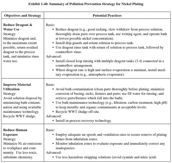
1.11.1 Dragout and Water Use Reduction
Rinsing following nickel electroplating should include dragout recovery and counterflow rinsing. Some survey
respondents have achieved zero water discharge using three to four recovery tanks connected in a counterflow
arrangement. Nickel tanks that run at a low temperature may not evaporate sufficiently for the dragout to be
completely fed back. In this case there are several methods (e.g., reverse osmosis, and evaporation) that can
concentrate the rinse water before return. Recovery rinsing will accelerate the buildup of
impurities, which must be dealt with (see bath maintenance); otherwise, bath disposal or recovery will be necessary.
A drag-in/dragout configuration can also be employed; note however, an important warning when considering this
approach. Dilute nickel solutions have been known to cause passivity of components, particularly when stray DC
current is possible. To avoid this problem, use a non-metallic drag-in tank.70
70 (Fisher, Bryan, Avoid nickel plating losses – Protect the environment and improve
profitability (extended version), Products Finishing Magazine, Sept. 2005.)
When workloads are continuous, water use control can be achieved simply with flow restrictors and by closing water valves when plating lines are idle. However, for nickel lines that are operated intermittently, additional controls are needed, such as conductivity controls or timer rinse controls. For final rinses following nickel plating, a commonly accepted conductivity range is 300 to 600 µmho.
One benchmarking survey company that has closed-loop rinsing employs three final rinses following nickel plating that are organized in a counterflow arrangement. This company also has a separate holding tank. Deionized water is fed to the last rinse and counterflows to the first rinse. The solution in the first rinse flows to a holding tank. The holding tank provides flow equalization for the deionized water flow rate and the evaporation rate in the plating tank. During the work week, the quantity of solution in the holding tank increases. Over the weekend, the idle nickel plating tank is kept at its normal operating temperature so that evaporation continues. During this time, a significant percentage of the solution in the holding tank is transferred to the plating tank. The return flow is pumped through a carbon filter, thus providing solution maintenance.
On July 1, 2008 EPA published the National Emission Standards for Hazardous Air Pollutants for Plating
and Polishing Operations.71 This rule impacts many metal finishing operations (EPA
estimates 2,900 facilities). It applies to facilities with plating, polishing or thermal spray processes that
contain cadmium, nickel, lead, manganese and/or chromium. (The rule will not apply to chromium anodizing and
electroplating, which are covered under a previous rule.)
71 (National Emission Standards for Hazardous Air
Pollutants: Area Source Standards for Plating and Polishing Operations; Final Rule, Federal Register July 1,
2008.)
With this regulation EPA did not establish emission limits for plating and polishing operations as they did with chromium plating, but instead required plating and polishing facilities to implement specific pollution prevention (P2) and control practices that are related to air emissions, dragout and rinsing:
- minimize bath agitation when removing tank objects
- maximize dripping of bath solution back into tank by extending drip time when removing the tank objects and using drain boards (i.e., drip shields)
- optimize the design of barrels, racks, and parts to minimize dragout of bath solution
- use a wetting agent or fume suppressant in the nickel electroplating bath
1.11.2 Chemical Recovery
One benchmarking survey respondent uses an ion exchange system for recovering nickel. This company's plating tank is followed by three rinses, connected in a counterflow configuration. A conductivity probe is present in the first rinse, nearest the plating tank (the most concentrated rinse). When the conductivity reaches a set point, solution in the first rinse is transferred to the ion exchange holding tank (220 gal). This flow is balanced by the addition of deionized water to the last rinse. The solution in the ion exchange holding tank is pumped through dual filters and the ion exchange column, which contains a cation bed that retains the nickel. The ion exchange unit is regenerated with sulfuric acid, and nickel sulfate is eluted. A small volume of hydrochloric acid is added to the recovered solution to destroy organics. The resulting nickel sulfate is tested using a Hull cell, and is subsequently used to replenish the plating bath. The water processed through the ion exchange unit is treated by a second ion exchange step to remove any residual nickel, and is then discharged to sewer, without the need for conventional treatment. Regenerant from the second ion exchange unit is recycled off-site.
In-process recovery (i.e., connected to the rinse system) is often used with nickel electroplating. The most common technology employed is the atmospheric evaporator. This technology is typically used in conjunction with recovery rinsing. Other applicable technologies include vacuum evaporators, ion exchange, electrowinning, reverse osmosis, and electrodialysis. Each of these technologies has both advantages and disadvantages:
- Evaporation. Atmospheric evaporations are relatively inexpensive and simple to operate. They are capable of recovering over 90% of nickel dragout and concentrating the nickel to 40 g/l Ni or more. Evaporators do not generate a waste stream like most other recovery technologies. One drawback is that all dissolved materials (including degraded brighteners) are recovered, which increases the need for bath maintenance. In addition, vacuum evaporators are expensive and are relatively complicated to operate and service.
- Ion Exchange. IX is capable of 97% recovery of nickel and it yields a relatively high concentration product stream (up to 40 g/l Ni). The IX resins must be periodically regenerated with acid (sulfuric or hydrochloric, depending on nickel bath chemistry), which creates a wastestream that must be treated. Some areas of the country have IX services that will regenerate columns off-site.
- Electrowinning. EW is relatively easy to operate and maintain. This technology has been applied to nickel, although it is better suited for recovery of other metals such as copper and precious metals. EW is not capable of removing nickel to low concentration levels, and the recovered nickel is difficult to harvest and reuse.
- Reverse osmosis. RO is capable of recovering over 90% of nickel while rejecting almost all dissolved materials, including brighteners (both usable and degraded). RO produces a recovery stream containing 10 to 20 g/l of nickel. The process could require an evaporation step if there is insufficient tank evaporation. The main weaknesses of RO are limited membrane life, the generation of a significant reject stream that contains some nickel and must be treated, and the loss of expensive brightener chemistry.
- Electrodialysis. ED can achieve 95% recovery of nickel. It concentrates the nickel salts sufficiently that in most cases the product stream can be returned directly to the plating tank. It has approximately the same cost as RO, and membrane replacement is a concern.
1.11.3 Additives
Anti-pitting agents are used to lessen pitting in nickel electroplating. The agent promotes the release of gas bubbles from the surface of the part. Anti-pitting agents also reduce surface tension of the solution, which, in turn, will help solution drain from the part, minimizing dragout.
1.11.4 Bath Maintenance
The key aspects of P2 for nickel electroplating operations are preventing bath contamination and maintaining the bath. Some important considerations and alternatives are discussed below.
During electroplating, the nickel anode dissolution efficiency is 100%. The cathode efficiency of nickel plating is typically 95–98%. When a moderate to high concentration of bath contaminants is present, the cathode efficiency can drop below 90%. This situation may cause the nickel content of a bath to increase over time, especially when recovery rinsing is used. To prevent the wasteful buildup of nickel metal, it is important to eliminate all sources of contaminants in the nickel plating bath. Even when contaminants are kept to a minimum, closed-loop nickel systems will generate an increase in nickel concentration. The holding tank concept used by one respondent (described under Water Use Reduction) may help in dealing with this problem. Copper anode bus bars can be a source of copper contamination, which is quite detrimental in nickel plating. A number of options are available that reduce the introduction of copper contamination in nickel plating:
- Wrap bus bars with a plating grade of nonadhesive vinyl tape, except for contact areas
- Plate copper bars with nickel
- Install PVC drain boards over the anode bars.
Parts fallen into the tank are a significant source of contamination and should be removed quickly. An inexpensive tank magnet can be used for retrieving ferrous parts. A siphon hose or makeshift shovel can be used to remove non-ferrous materials.
During electroplating, the organic additives of nickel baths produce decomposition products that, if allowed to accumulate, can result in unacceptable plating. To help reduce the occurrence of these problems, finishers treat the solution using activated carbon, alone or in combination with hydrogen peroxide or potassium permanganate. If excessive carbon treatment is needed on a regular basis, the plating procedures should be reviewed to identify sources of organic contamination (e.g., drag-in or poor cleaning), and these should be eliminated.
Not all activated carbon products are suitable for use with nickel plating solutions. Suppliers of proprietary
additives can recommend a suitable grade. The quantity of carbon required will depend on the degree of
contamination.72
72 (Bless, Diana R., A Review of Nickel Bath Life Extension, Nickel Recovery and
Copper Recovery from Nickel Baths, Plating and Surface Finishing, April 2000.)
Although effective, carbon treatment increases downtime, creates liquid and solid waste, and increases employee
contact with toxic materials. In addition, the treatment process can result in solution losses up to
20%.73 There are alternatives to using activated carbon for organics removal. At least one supplier
offers a polymeric resin system that provides continuous nickel solution maintenance.74 The resin is
regenerated with mild alkaline solution and is reused. Another alternative technology recently investigated is use
of catalyzed hydrogen peroxide.75 During long-term testing of this process, it significantly outperformed
conventional hydrogen peroxide/carbon treatment, especially with regard to detrimental organic breakdown
products.76
73 (Fisher, Bryan, Avoid nickel plating losses, Guidelines to help prevent
the loss of nickel and its salts from the finishing shop, Products Finishing Magazine, Sept. 2005.)
74 (Atotech, Nikotect Adsorber System: Advanced Maintenance and Recycling
Technology for Bright Nickel Plating Processes, www.atotech.com.)
75 (Forth, Peter, Vibert, Art, Busch, Madeline and Stevenson, Sarah,
Treatment and Control of Nickel Electroplating Baths Using Catalyzed Hydrogen Peroxide, 23nd AESF/EPA
Conference, Jan. 2002.)
76 (Forth, Peter, No More Activated Carbon Treatments Required, Products
Finishing Magazine, May, 2005.)
Electrolytic treatment (dummying) can be effectively used to remove copper, zinc, iron, and excesses of certain organic brightening agents. A corrugated cathode is used in this treatment, and the bath is electrolyzed at 2 to 5 amps per square foot (asf). One survey respondent indicated that their facility has implemented continuous electrolytic treatment by adding a holding tank with a separate rectifier. Solution from the bath is transferred continuously to the holding tank and returned to the bath. The circulation loop includes carbon filtration.
Metal precipitation or "high pH" treatment can be used for removal of trivalent
chromium, aluminum, copper, iron, and silicates. Removal is accomplished by transferring the solution to a batch
treatment tank, raising the temperature (145–150°F), and adding a slurry of plating-grade nickel carbonate (raises
pH to 5.2). Hydrogen peroxide can be added to help oxidize the iron. The solution is filtered and returned to the
plating tank. The solution may then be electrolyzed at low current density until deposit quality is
acceptable.77 One survey respondent pointed out that high pH treatment results in solution loss, sludge
creation, and holding tank cleaning. Instead of performing this type of bath maintenance, this company periodically
decants a portion of the bath and reuses it on-site or recycles it off-site.
77 (Dibari, George A., Nickel Plating, Elsevier Metal Finishing Guidebook and
Directory, 2008.)
1.11.5 Additional P2 Methods
Benchmarking survey respondents listed additional P2 methods for nickel electroplating. These include:
- Converting from a nitric acid strip to a less hazardous and regenerable sulfuric acid/ peroxide process
- Replacing cyanide stripper with non-cyanide stripper
- Employing equipment rotators to improve drainage of dragout
- Using a closed-loop chiller system to control bath temperature
1.11.6 Air Emissions
A cold, still, nickel plating bath most likely does not generate any detectable nickel-bearing mist. Also, given that the deposition efficiency of a nickel electrolyte is in the order of 96-98%, (and therefore there is very little gassing from electrolysis), the application of direct current for deposition is unlikely, by itself, to increase the presence of nickel in the immediate atmosphere by any significant quantity (Fisher). However, heating the solution and applying air agitation can cause significant nickel losses to the atmosphere. To reduce losses, consider operating the bath at the lowest practical temperature, using mechanical agitation (i.e., solution pumping or cathode bar movement). In addition, although not specifically used for nickel plating as yet, tank covers could be used to assure compliance with any new air pollution control rule (see the anodizing section for discussion of EED covers).
1.11.7 Nickel Strip Acid Recovery
The most common nickel stripping solution is nitric acid. During use, acid is consumed and the rate of stripping declines. Eventually the solution must be removed from service and disposed of (off-site disposal can run as high as $5.00 per gallon). At this point, some active nitric acid is still present, although it is diluted by the unusable portion. One method of maximizing the life of the nitric acid strip is to employ diffusion dialysis, a membrane separation process commonly used for maintaining sulfuric acid anodizing baths.
When recovering acids using diffusion dialysis, an anion exchange membrane acts as a semi-permeable barrier placed between a flowing water stream and a flowing acid solution containing dissolved metals. The anion exchange membrane has fixed positive charges located on its surface. These positive charge centers attract the negatively charged anions in solution that come into close contact with the anion exchange membrane surface.
With nitric acid baths, the overwhelmingly predominant anion is the nitrate ion (NO3-1). As the
nitrate ions in the acid solution are attracted to the membrane, they are also driven by the concentration
difference to diffuse across the membrane to the water side. Simultaneously, the Law of Electroneutrality (in
solution total charge must balance to zero) requires that the transfer of every nitrate ion (negative) into solution
is accompanied by the transfer of one unit of positive charge. Positively charged ions such as Ni+2 or
other metal ions, are strongly inhibited from crossing the positively charged membrane because of the repulsion
between like charges. The hydrogen ion, present in the acid solution as H3O+ ions, is also
positively charged, but is able to cross the membrane with very little hindrance. This is due to the high
concentration of hydrogen ions in the acid solution, the small size of the hydrogen ion, and the ability of the
hydrogen ion to transfer rapidly between one water molecule and another. The net effect is that both components of
the nitric acid molecule, the hydrogen ion and the nitrate ion, diffuse across the membrane faster than the
dissolved nickel. Typically, 80-90% of the acid is recovered, with 70-90% of the dissolved metals removed.
78
78 (Capalbo, Ralph, New Method for Recycling Acids at New Method Plating,
Products Finishing Magazine, May 2004.)
1.12 TIN AND TIN–LEAD PLATING
There are several pollution prevention opportunities for tin and tin–lead plating operations. The most common focus on alternative processes for tin–lead, reducing water use, plating solution control and maintenance, and recovery. Exhibit 1-41 summarizes the following discussion regarding pollution prevention strategies for tin and tin–lead plating.
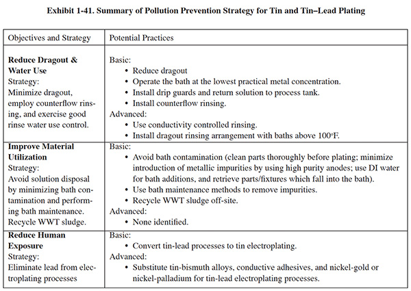
1.12.1 Alternative Processes
Tin–lead is commonly used by the printed wiring board (PWB) industry and for other electronics applications. In PWB manufacturing, tin is essentially just as effective as tin–lead as an etch resist and can replace tin–lead plating when solder-mask-over-bare-copper (SMOBC) is employed. Tin-only baths can be used as a substitute in many other cases, although not for all current tin–lead applications. Emerging substitute technologies include tin–bismuth alloys, conductive adhesives, and nickel–gold or nickel–palladium electroplating.
1.12.2 Dragout and Water Use Reduction
Metal finishers can achieve water use reduction in tin and tin–lead plating by minimizing dragout, using multiple rinse tanks, and controlling water use. To reduce dragout, efforts should focus on rack design, part orientation, and dwell times. With continuous processes, such as reel-to-reel plating for electronics, an air knife can be used to further reduce dragout losses.
To reduce water use while still meeting rinsing needs following tin or tin–lead plating, a two-stage counterflow rinsing configuration will typically suffice. One survey respondent indicated that they use three-stage rinsing after tin plating. A dragout tank for recovery can be used with baths operated above 100°F (e.g., potassium stannate or sodium stannate).
On continuous production lines, where rinse water needs are relatively stable, flow can be controlled easily by periodically monitoring rinse water conductivity and manually adjusting flow, using a valve. If workflow is sporadic, a conductivity control or timer rinse control should be considered. These devices help to match rinse water use and production flow. For final rinses following tin and tin-lead plating, commonly accepted conductivity ranges are 70 to 500 µmho (final tin alkaline rinses should be operated below 340 µmho).
On July 1, 2008 EPA published the National Emission Standards for Hazardous Air Pollutants for Plating
and Polishing Operations.79 This rule impacts many metal finishing operations (EPA
estimates 2,900 facilities). It applies to facilities with plating, polishing or thermal spray processes that
contain cadmium, nickel, lead, manganese and/or chromium. (The rule will not apply to chromium anodizing and
electroplating, which are covered under a previous rule.)
79 (National Emission Standards for Hazardous Air Pollutants: Area Source
Standards for Plating and Polishing Operations; Final Rule, Federal Register July 1, 2008.)
With this regulation EPA did not establish emission limits for plating and polishing operations as they did with chromium plating, but instead required plating and polishing facilities to implement specific pollution prevention (P2) and control practices that are related to air emissions, dragout and rinsing:
- minimize bath agitation when removing tank objects
- maximize dripping of bath solution back into tank by extending drip time when removing the tank objects and using drain boards (i.e., drip shields)
- optimize the design of barrels, racks, and parts to minimize dragout of bath solution
- use a wetting agent or fume suppressant in the tin/nickel electroplating bath
1.12.3 Bath Maintenance
Bath maintenance can reduce the need to discard process solutions. The primary source of tin and tin–lead bath contamination is metal impurities from anodes. These contaminants can be partially avoided by purchasing high-quality, low-impurity anodes.
Dissolved metal impurities can be removed using low current density electrolysis (dummying). Stannic ion is an unavoidable contaminant that must be maintained at relatively low levels by performing continuous filtration and chemical treatment. Fluoborate baths are particularly subject to buildups of sludge. Therefore, continuous in-tank or external filtration during operation is recommended with these solutions. Organic bath additives are decomposed during plating and will concentrate in the bath. A carbon treatment can be performed on tin–acid and tin–lead baths to eliminate all organics. Fresh organic additive is then reintroduced.
Stannous tin (stannite) is a contaminant in a stannate solution. It can break down to produce sludge by forming
colloidal tin. The presence of stannite may also produce rough, spongy deposits. To convert stannite back to
stannate, dilute a small amount of hydrogen peroxide with water to make a 10% solution. Add this to the plating tank
with a lot of agitation. After addition of the peroxide, the plating solution will need to be dummied until the
excess peroxide is converted to water.80
80 (Altmayer, Frank, Advice and Council: Tin
Basics, Plating and Surface Finishing, May 2005. )
Process control for methanesulfonic acid systems using insoluble anodes, where tin is not automatically replaced,
often involves bath bailouts to maintain a sufficiently high tin concentration (due to the fact that all of the tin
that is plated comes from the tin methanesulfonic acid). The bailouts result in high production of F006 wastewater
treatment sludge. A novel approach to the problem using a membrane technology was developed at a reel-to-reel shop
that uses a tin replacement cell hydraulically connected to the plating tank. The system is shown in Figure 12. In
the plating tank, oxygen is liberated at the insoluble anode and tin is plated on the cathode, resulting in a lower
tin concentration in solution and an increase in the free acid concentration. The solution is continuously
re-circulated from the plating cell to the anolyte chamber of the tin replenishment cell via the lower plating sump
(not shown). In the tin replenishment cell, tin is electrochemically dissolved into the anolyte at the soluble tin
anode, and it combines with the free acid produced in the plating cell, liberating hydrogen ions. The hydrogen ions
pass through the membrane into the catholyte chamber, which is filled with methanesulfonic acid at approximately the
same concentration as the plating bath. The ions replace those lost to the evolution of hydrogen gas at the tin
replacement cell cathode. Some tin ions pass through the membrane (approximately 5%), and are deposited at the tin
replacement cell. Bath bailouts were eliminated and the process control of the solution was simplified. Only small
adds of tin methanesulfonic acid were required to make up for drag out losses. Waste treatment and sludge disposal
costs were reduced, due to elimination of bail-outs. The net annual savings after energy and membrane replacement
costs was in excess of $40,000. The capital cost of the equipment was less than $30,000.81
81 (William Copping; SUR/FIN 2003; 2003 Jun Novel Technique for
Replenishing Tin & Controlling Tin Baths)
1.12.4 Chemical Recovery
Various chemical recovery technologies have been used with tin and tin–lead electroplating. The most frequently used technologies are ion exchange, electrowinning and evaporative recovery.
1.12.5 Disposal of Spent Baths and Sludge
Tin and tin–lead sludges do not have significant economic value and are by themselves usually not recycled off-site. However, one survey respondent indicated that their facility treats tin-bearing rinse waters and spent baths, and sends the resultant hydroxide sludge to a reclamation site.
1.12.6 Tin Strip Recovery
Off-site disposal or on-site treatment of spent nitric acid tin stripping solutions can be expensive. Diffusion
dialysis has been used for these baths, but with limited success.82 A novel approach to this problem was
developed where a caustic stripper was substituted for the conventional nitric bath and electrowinning was used to
capture the metal.83 Using this process, tin concentrations were reduced from about 150 g/l to 30
g/l.
82 (Ford, Christopher and Coletta, Ted, Reclamation of Nitric Acid from Solder
Strip, The Massachusetts Toxic Use Reduction Institute, 1995.)
83 (McKesson, Doug, Miracles in Tin Stripping, PC Fab Magazine, June
1999.)
1.13 ZINC PLATING
Operating environmentally efficient zinc electroplating processes begins with the selection of the plating bath. Twenty years ago, most zinc plating was carried out with cyanide baths. Today, low-cyanide and non-cyanide plating solutions are available that meet most metal finishers' needs.
Many of the survey respondents identified conversion from cyanide to non-cyanide as a major P2 improvement. Several of the respondents indicated that complete conversion to non-cyanide was not possible due to special work requirements. In such cases, companies have converted one or more tanks to non-cyanide and maintain a single zinc cyanide tank, or have switched to a low-cyanide chemistry.
Zinc cyanide plating baths are significantly less affected by poor cleaning than alkaline non-cyanide baths. One respondent noted that it is possible to operate a zinc cyanide bath with floating oil. In contrast, alkaline non-cyanide zinc plating requires extensive cleaning, similar to that needed for nickel plating directly onto steel. Exhibit 1-42 summarizes the following discussion regarding pollution prevention strategies for zinc plating.
1.13.1 Bath Maintenance
Even with non-cyanide baths, solution chemistry control must be exercised to minimize pollution. Several survey respondents indicated that zinc plating bath control was an integral part of their P2 approach. Several survey respondents indicated that the use of automatic chemical bath additions improves control. One survey respondent controls the use of brightener by storing the chemical in totes, which platers cannot access without permission. This restriction has reduced brightener usage by 30%. Important aspects of solution control include controlling metal buildup, making proper additions of bath components, and contamination control. Metal buildup can occur when zinc anodes dissolve during idle times. This situation can be avoided by removing the anodes from the solution when it is not in use. This practice is more effective for alkaline baths than for zinc chloride baths.
Zinc metal concentration can also be controlled in cyanide and alkaline non-cyanide plating solutions by using inert anodes (i.e., steel or carbon). Using deionized water for evaporative makeup, retrieving fallen parts or racks, filtration, and removing metallic impurities can improve contamination control. One respondent uses permanent media filters rather than disposable filters to reduce the quantity of waste being discarded. Electrolysis is used to remove lead and cadmium. Various chemical treatments followed by filtration are also used to remove metallic impurities, including:
- Sulfide reagents (lead, cadmium removal)
- Sodium hydrosulfite (chromate removal)
- Zinc dust (cadmium and lead removal)
- Hydrogen peroxide (iron removal).
Activated carbon treatment is employed to remove organic impurities (cleaner components, plasticizers, and decomposed additives). One survey respondent completely removes plating solution from their zinc plating tank when it is not in production mode. This company indicated that this practice prevents buildup of organics on the anode baskets, extends the service life of anode baskets, prevents zinc metal buildup in the plating bath, and provides a safeguard against tank failure.
1.13.2 Dragout and Water Use Reduction
Rinsing following zinc plating presents challenges to the metal finisher. Due to the relatively low temperature of the zinc bath, there is limited opportunity for use of drag-out recovery rinsing. However, some proprietary zinc chloride baths can be operated as high as 130°F, which is sufficiently high to make recovery rinsing feasible and effective. One respondent uses an atmospheric evaporator to increase evaporation and recover plating solution. Although several survey respondents indicated they employ recovery rinsing, most rely more on several other aspects of rinsing: dragout minimization, counter-flow rinsing, and water use control. Survey respondents have implemented dragout reduction by:
- Increasing dwell time
- Rotating racked parts for better drainage
- Redesigning barrels to reduce the volume of trapped solution
- Rotating barrels above the plating tank after they exit the solution (see draining/rinsing over the plating tank)
- Training operators
Operating the zinc plating bath at the lowest practical metal level or using excess wetting agent will also decrease dragout losses. Numerous respondents cited water use control as a key aspect of pollution prevention on the zinc plating line. The equipment employed includes flow restrictors, conductivity controls, shut-off valves, and timer rinse controls. For final rinses following zinc plating, commonly accepted conductivity ranges are less than 630 µmho for zinc acid and 300 to 1,200 µmho for cyanide zinc. Although the traditional dragout recovery rinse is not used by many of the benchmarking survey respondents, at least two companies employ drag-in/ dragout recovery rinsing tanks to recover a portion of the dragout.
1.13.3 Chemical Recovery
Various chemical recovery technologies have been used with zinc plating, although there are fewer total applications than with most other plating metals. The most frequently used technologies are evaporative recovery and electrowinning. Ion exchange has also been used, but with less success than the other two recovery technologies.
Zinc is the least recovered of the common electroplated metals due to:
- technology issues -- recovery technologies used by metal finishers are less efficient and effective with zinc than other metal applications
- lack of incentive – the relatively low value of zinc and the relatively high zinc effluent discharge standards (especially in comparison with local standards for metals such as chromium, cadmium, and lead).
Off-site recovery, although not within the true definition of pollution prevention, is highly applicable to zinc wastewater treatment sludges, particularly when they are not combined with wastes of other metals. There are two reasons that make off-site recycle an attractive option:
- When wastewater treatment sludge is generatedfrom segregated zinc cleaning, plating (on carbon steel) and/or zinc stripping processes, that sludge is exempt from the scope of RCRA hazardous waste F006 (40 CFR 261.31). To obtain this status, any chromating wastes, if present, would have to be handled on a segregated basis. Therefore, unless the sludge is a characteristic hazardous waste (e.g. corrosive), then it is non-hazardous, and the rules that apply to management, transportation and disposal are relaxed.
- There are a number of licensed facilities around the U.S and Mexico that recycle zinc wastes. Zinc sludges can be easily recycled into usable industrial products, including construction material.
Recycling of zinc wastes is carried out by large zinc waste processing facilities in the U.S. and Mexico that employ rotary kilns or other technology. The most common waste processed by these facilities is electric arc furnace dust generated by steel making/recycling processes. Zinc electroplating sludges are an ideal secondary feedstock for the rotary kilns. The kilns utilize a high temperature metal recovery (HTMR) process for zinc recycle. At temperatures over 2000 °F, valuable metals are volatilized and captured for further processing into refined metal products, which are sold for industrial uses. The slag from the kiln produces an iron-rich material (IRM) which can be used as construction material or as filter media in wastewater treatment applications.
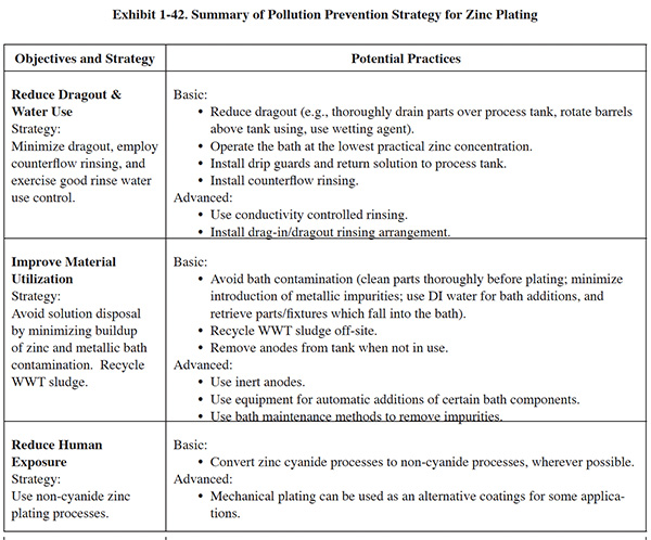
1.14 OTHER METAL FINISHING PROCESSES
This section contains benchmarking survey respondents comments related to processes other than those specifically covered in previous sections. Readers may find some of these comments useful when evaluating their own practices and identifying new opportunities for pollution prevention. The comments are essentially unedited except for spelling and other minor corrections to improve readability. Square brackets denote paraphrasing of respondent comments, or editorial comments.
Readers should fully investigate and evaluate any options before implementing them.
1.14.1 Phosphating
The following comments are pollution prevention methods benchmarking survey respondents used to address phosphating.
- Automatic additions to phosphate baths— resulting in less human exposure.
- Changed to a chemistry that generates only one quarter of the sludge previously produced. Iron control system used on zinc phosphate bath.
- Installed motorcontrolled hoists to reduce dragout. Use counter flow rinsing. Conducted operator training. Installed bulk storage system and eliminated use of waste drums.
- Filter phosphate solution so we don't have to decant periodically. [One respondent indicated that this is not a very effective practice.]
- Converted existing rinse tanks to counterflow.
- Use water restrictors. Increased dwell time. Installed drip pans. Use vacuum evaporator for recovery. Installed oil skimmer and microfilter on cleaner. Reduced concentration of chromium in sealers (magnesium phosphate) and use non-chromium sealers (zinc phosphate).
- We have tried non-chromium sealers and will move into one shortly.
- Increased analysis of phosphate solution.
- Added acid filter. Increased analysis and bath maintenance.
- Use counterflow rinses. Use acid wetters.
- Use manual titration for prep and phosphating baths. Substituted water-soluble oil whenever customer requirements permit. Implemented operator training to minimize dragout and water use and to extend bath life.
- Use counterflow rinsing.
- Installed counterflow rinses to reduce rinse water use, installed flow meters at all rinse tanks to reduce water use, installed oil separator on the cleaner system. Installed heat exchangers to heat zinc phosphating bath in place of live steam, saving zinc phosphate bath from displacement overflow.
1.14.2 Passivation
The following comments are pollution prevention methods survey respondents used to address passivation.
- We are pilot testing of an acid sorption unit.
- Extended dwell time over process tank.
- Use deionized water for bath makeup. Deionized water used throughout passivation line.
- Maintain racking orientation to achieve best drainage; allow sufficient drainage over process tanks.
- Replaced nitric acid process with a proprietary citric-acid-based process. The new process is less toxic and dangerous; however it is more expensive to operate. [Another survey respondent is testing a citric acid process.]
- Installed oil skip process to reduce the oil flowing into the system, thereby reducing chemical usage.
- Changed acids and reduced the quantity of acid on site.
1.14.3 Black Oxide
The following comments are pollution prevention methods survey respondents used to address black oxide.
- Use dead rinses. Reduced acid concentration in pickle. Use flow restrictors.
- Use deionized water for rinsing and replenishment.
- Use counterflow rinsing.
- More efficient burners purchased (natural gas reduction).
- Flow restrictors on water rinses. Plumbed existing rinse tanks to counterflow.
- Use oil recovery drip trays and recover oil from spin dryers.
- Water restrictors, dwell time, drip pans, caustic cleaner skimming and microfiltration, elimination of solvent-based cleaners, lower-VOC water-based oils, cold evaporation of water from waste production oils (a 65% reduction).
- Automatic additions to the bath resulting in less human exposure. Better method for disposing of the sludge generated in the bath through waste treatment.
- New line installed—less hydroxide loss and better process control.
- Basic P2 methods. Equipment rotators for better drainage, cleaner recycling.
1.14.4 Electropolish
The following comments are pollution prevention methods survey respondents used to address electropolishing.
- Save rinse; closed-looped rinse system with evaporator used to maintain temperature of process tanks.
- Found end users for used electropolishing solution. Closed manufacturing loop to purify acidic rinse water. Sludge from clarifier is Class V non-hazardous.
- Rinse water is reused for different rinses up the line.
- Cover tanks when not in use to prevent adsorption of moisture from the air.