Hard Chrome Plating Training Course
Appendix 5. Plating Parts Using a Plating Log
General
Plating logs, sometimes called travelers, are a set of paperwork on which is recorded information about the plating process for a particular part. If a part is mis-plated, this information can be used to help figure out what went wrong. Also, the information can be used to help establish trends such as plating rates.
The design of plating logs varies from shop to shop. The log found in this appendix is only an example. Your shop will probably use something similar, but it could ask for different types of data.
In this example, we'll examine the benefits and use of plating logs. All of the information on the plating log pertains to the particular part being plated, and each part has its own log. It takes some time to fill out a log form, but the time is well spent. The log increases the chances for a successful plating cycle for the part at hand, and future parts that may have the same size, shape or base metal.
Some parts of the plating log are filled out before the part is plated. For example, customer and manufacturer names, part types and numbers, and preplate and required postplate dimensions can be recorded.
Then, the plater can calculate the plated surface area, required deposit thickness, rectifier amperage and plating time. The reverse etch and plating voltage, amperage and times are added to the form as the part is processed.
After plating, the postplate dimensions are recorded, as well as any helpful information about the plating results. Was the chrome bright and adherent? Were there any visible defects? You can even extend the postplate data to include additional information. Was the chrome thickness and distribution good enough to allow the grinding operation to get the part to the desired finish size?
Example
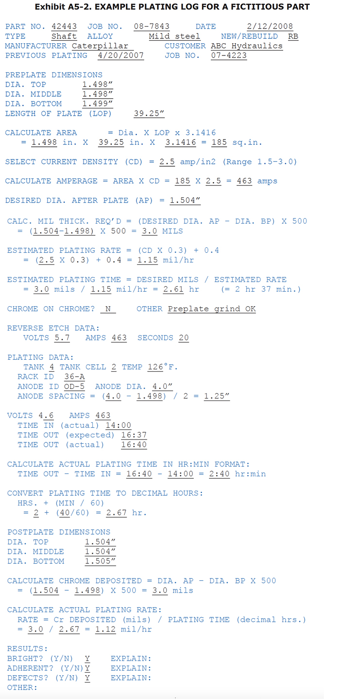
Let's process a fictitious part (Exhibit A5-1) using a plating log (Exhibit A5-2) designed for cylindrically-shaped parts, like shafts or rods. Our fictitious part is a hydraulic rod or piston. The rod is about an inch and a half in diameter with a 39-1/4" length of plate. The rod is to be OD plated in a 4" diameter conforming anode.
Every plating log should include the general information described above, such as part and job number and information about the part type and alloys. The part manufacturer and plating shop customer are also recorded.
The log should record the critical preplate dimensions. It's a good idea to measure several areas on the part,
especially those areas that are significant to the fit or function of the part. If you suspect the part is out
of round, it's a good idea to measure each area twice, at 90 degrees from the original measurement.
When plating by amps, you must first calculate the plated surface area. With cylindrically shaped parts, the formula is simply: DIAMETER x LENGTH OF PLATE x Pi.
CALCULATE AREA:
Dia. X LOP x 3.1416 = 1.498 in. X 39.25 in. X 3.1416 = 185 sq. in.
Next, the plater needs to pick a good current density for the part. It should be in a range that has proven itself with previous plating cycles of the same or similar parts. The chosen current density (CD) should not be so high that the plating amperage exceeds the current carrying capability of the rack or anode, or the rectifier capacity. Also, it should be appropriate for the bath temperature, because a mismatch may result in dull, soft chrome. In our example, a current density of 2.5 amps per square inch was chosen.
Once you have selected a CD, multiply it by the plated surface area to get amps:
CALCULATE AMPERAGE:
AREA X CD = 185 X 2.5 = 463 amps
Usually, parts can be reverse etched and plated at the same amps. The amperage calculated here will be used to set the rectifier controls.
Then, decide what the desired postplate diameter should be. This postplate diameter typically includes extra chrome for grind stock. The chrome thickness can be calculated if the plater remembers that, with a diameter, you have to consider that the chrome thickness is building up on opposite sides of the round rod, and both add to the postplate diameter measurement.
CALC. MIL THICK. REQ'D:
(DESIRED DIA. AP – DIA. BP) X 500 = (1.504–1.498) X 500 = 3.0 MILS
The "500" factor in the mil thickness equation takes the diameter issue into account as it converts thousandths of inches into mils thickness. In the example, the diameter must grow 0.006" during plating, which takes 3 mils of chrome per side.
The formula for estimating the plating rate, as a function of current density, was determined by analyzing historical
data at a plating shop that plated mostly hydraulic rods in a single catalyst, sulfate-only bath. The parts were
all plated in cylindrically-shaped conforming anodes. If this formula does not work for your situation, try creating
your own formula by examining the plating rate achieved for various current densities. Plotting them on a graph
or using a curve-fitting program can help to create the equation that best represents the plating rate as a function
of CD.
ESTIMATED PLATING RATE:
(CD X 0.3) + 0.4 = (2.5 X 0.3) + 0.4 = 1.15 mil/hr
Once the plating rate of deposition has been estimated, you can estimate the plating time by dividing the desired mil thickness by the estimated mil per hour plating rate of deposition.
ESTIMATED PLATING TIME:
DESIRED MILS / ESTIMATED RATE = 3.0 mils / 1.15 mil/hr = 2.61 hr
It's a good idea to record all of the data shown in Exhibit A5-2). Since any chrome-on-chrome procedure demands different warmup, etch and ramp procedures, the log should indicate whether or not the chrome is to be deposited over existing chrome or the base metal.
Always record accurate reverse etch information, since an under-etch or over-etch can cause many plating defects. Since the chromic acid solution in the chrome plating tanks may differ in regards to catalyst ratios and contamination levels, the tank number should be recorded, as well as the location in the tank. Rack and anode IDs should be noted, and the anode size and anode-to-cathode spacing. It is often helpful to compare, over time, the voltage needed for a certain part and anode combination. If the voltage is much higher than previous plating cycles at the same amperage, the bath resistance may have increased due to high trivalent chrome or metallic impurities, or low chromic acid concentration.
Finally, always record the start and stop times for every part plated. Without this information, it will be impossible to calculate the deposition rate for the plating cycle.
Subtract the start time from the stop time to calculate the plating time. Then, convert the hours-and-minutes format to decimal hours as shown. This will be used later when calculating the actual rate of deposition.
Record the postplate dimensions, being careful to measure the part at the exact same locations that the preplate measurements were taken.
With a round part, the postplate diameter minus the preplate won't really give you the chrome thickness. Rather, it will give you twice the thickness, since the chrome deposited on opposite sides is being measured simultaneously by the micrometer. The last formula the in Exhibit accounts for this and expresses the chromium thickness in mils, rather than thousandths of an inch.
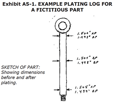
CALCULATE CHROME DEPOSITED:
DIA. AP – DIA. BP X 500 = (1.504 – 1.498) X 500 = 3.0 mils
The plater should take the time to calculate the actual rate of deposition for this plating cycle, and note the condition of the deposit. The information can be useful for future parts, or for alerting the plater to an unusually slow rate, indicating a problem of some sort.
Don't rely on your memory for storing information, it will result in inaccurate results. When you make measurements, make a drawing showing where on the part that the measurements were taken.