
Hard Chrome Plating Training Course
Section 3—Process Chemistry and Equipment
Overview
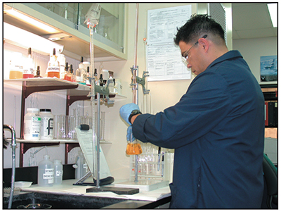
Exhibit 3-1. Laboratory technician conducting solution testing.
In this section, we'll talk about the processes and equipment that make up a typical hard chrome plating line. It is a long section, because we have a lot of details to cover. First, we'll discuss some of the most widely used plating baths, how they differ, and what advantages and disadvantages each type of bath provides.
Next, we'll talk about the electrical side of hard chrome plating. We'll see that the alternating current, or AC, that the electric company delivers to the plating shop must first be converted to direct current, or DC, before it can be used for stripping, cleaning, reverse etching or plating. We'll look at several types of DC power supplies that have had widespread use in hard chrome plating lines.
Next, we'll talk about tank design. In particular, we'll discuss examples of different ways to set up the permanent electrical connections using copper bars or rods, called "bus bars" on top of a chrome tank. This tank top bus bar system will vary according to the type of anodes used, type and size of parts plated, and other factors. Historically, two popular designs have been called the "3 bus bar" design and the "2 bus bar" design, and we'll look at each of them.
Then we'll discuss the various process tanks involved for pretreatment and hard chrome plating.
Next, we'll turn from the tanks to their contents, starting with the anodes that serve as the counter-electrode when parts are plated. Because of their importance, we have included a lengthy discussion of lead alloy anodes. Significant performance and deposit control gains can be made when using conforming anodes instead of the older stick anodes that were standard for decades with 3 bus bar tank designs.
We'll then cover how the plating solutions are heated. Solution heating is needed because hard chrome plating, and some pretreatment processes, occur at temperatures above ambient. For example, the hard chrome plating tank might be operated at 130 degrees Fahrenheit.
Chrome platers invest a lot of energy in heating their tanks. Solution cooling is usually required as well for a chrome bath. This is due to the fact that the hard chrome plating process has such a low current efficiency. This means that only a small percentage of the power from the rectifier deposits chromium. The rest of the current goes into other processes, like overcoming the resistance of bath to the flow of electricity, which builds up heat in the bath, and evolving hydrogen gas at the part and oxygen gas at the anode, "electrolysis" processes that consume energy but don't plate metal.
In addition to heating the bath, platers have to keep the bath moving. Solution agitation is helpful in a hard chrome plating bath, because it leads to chemical and thermal uniformity in the bath, and also helps to dislodge hydrogen bubbles from the surface of the part. Agitation is helpful not only in the plating bath, but in the rinsing bath as well. Rinsing is greatly improved when rinse tanks are agitated.
Finally, this section covers the extremely important topics of exhaust ventilation and air pollution control. The health hazards associated with hexavalent chromium are widely known, and it is necessary to prevent release to the plating room atmosphere or outside air.
The scrubbers used for hard chrome plating have improved dramatically over the years because shops have come to recognize the health risks associated with hexavalent chromium and they are subject to increasingly more stringent governmental regulations.
We'll discuss mesh pad or composite mist eliminators, which are the most common, modern-day devices used to extract chromic acid mist from chrome plating tanks.
Another completely different approach to air pollution control is the use of covered tanks. One particular commercial technology employs a stainless steel tank lid that prevents chromic acid mist from escaping to the workplace. This technology is discussed later in the course.
Chromium—Chemical Terminology
 |
|
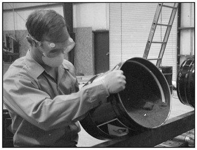
Exhibit 3-2. ADDING CHROME: Solid chromium trioxide is added to tank for original bath makeup, and then later to replace chrome that has plated out of bath (note the gloves, chemical goggles and dust mask). |
Before we talk about chromium plating baths let's review the various forms of chromium that we encounter in the plating shop.
First, a little chemistry. Chromium is a chemical element – a single type of atom. It is element number 24 in the periodic table of elements, with the abbreviation Cr.
Pure chromium is a metal, and it will not dissolve in water. The metal can react with strong oxidizing agents, which will strip some of the electrons off the chromium atoms. This turns them into charged ions, which can combine with ions of other elements to form compounds like salts and oxides. Many of these compounds will dissolve in water. So the first step in making up a chrome plating bath is to dissolve an appropriate chromium compound in water.
We're almost done with the basic chemistry, but here's one more item that will be useful to keep in mind. Some chemical elements are very particular about the number of electrons they will lose or gain to form an ion. Sodium, for example, the metal found in ordinary table salt, will always lose only one electron. Calcium, found in bones and teeth, will always lose two electrons – no more, no less. But chromium is a very versatile atom in terms of the number of electrons it is willing to lose. Stable chromium compounds can be produced from ions with two, three, four, or six missing electrons. Two of these forms are particularly important for platers. Chromium atoms with six missing electrons are called hexavalent chromium ions, from the Greek word for the number six, as in hexagon. It is typically written as Cr+6 or Cr VI, and is read as "Cr six" or "Cr Roman numeral six". Similarly, chromium atoms with three missing electrons are called trivalent, (Cr+3 or Cr III), from the Greek word for the number three, as in triangle.
So when we talk about hexavalent and trivalent chrome, remember, it's all chrome atoms, but in a different chemical state. You can convert one state to the other, or you can recover the neutral metal, by using chemical reactions or an electric current to change the number of electrons attached to the atom.
Now let's look at plating baths. The main ingredient of hard chromium plating baths is a hexavalent chromium compound called chromium trioxide, with the chemical formula CrO3. It is usually purchased in flake form. When chromium trioxide is mixed with water, the solution or bath is often referred to as chromic acid. Liquid chromic acid is commercially available, but it is less frequently used than the chromium trioxide flake.
During the chromium plating process, some of the hexavalent chromium is converted to trivalent chromium instead of depositing as chromium metal. In this form, it cannot be electroplated. Therefore, it is considered a bath impurity. We will discuss ways of preventing the buildup of trivalent chromium later in the course.
Types of Plating Baths in Common Use
Now that you have dissolved chromium trioxide in water, you have the beginnings of a chrome plating bath. But you're not ready to plate yet. The bath needs other ingredients if it is going to work.
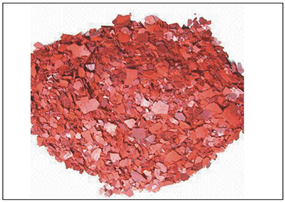 |
| Exhibit 3-3. Chromium Trioxide |
One important additional ingredient is called a catalyst. In any chemical reaction, a catalyst is a material that speeds up the reaction, but doesn't get used up – it either doesn't change during the reaction, or it changes temporarily, but cycles back to the way it began before the reaction is over. You don't have to keep on adding more of it (except for what gets dragged out of the bath), but if you haven't added it in the first place, the reaction might never get started. That's true of chrome plating – no catalyst, no plating.
The catalyst is the only extra ingredient we'll discuss in detail, but some baths contain other components as well. Many different chromium bath recipes have been developed over the years. We'll take a look at a few that use different catalyst systems.
After much competition during several decades among chemical suppliers promoting their various formulations, three popular baths have evolved. All are hexavalent chromic acid solutions. They are:
- the conventional or single catalyst bath,
- the mixed catalyst bath, and
- a new proprietary formulation that we will call the high-speed, non-etch bath.
The conventional bath was the earliest of these formulations to be developed, and it is still in wide use today. It is commonly used at military depots, aircraft overhaul facilities and job shops. It is called the "single-catalyst" bath, because it uses the sulfate ion as its only catalyst.
Another early bath contains the fluoride ion as an additional catalyst, and is called the "mixedcatalyst" bath. It has a higher efficiency and plates faster, but it can chemically attack areas of submerged steel that are not getting plated. It will also attack rack members and anodes at a faster rate than the non-fluoride baths.
The most recent bath is a proprietary formulation that is efficient and fast. It does not have the etching problems of the fluoride bath. But it's proprietary, meaning that the supplier won't tell you what's in it.
Conventional, Single-Catalyst Bath
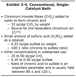
The conventional bath dates back to the 1920's, but is still among the most widely used baths in the world, due to its relatively low cost. It can be thought of as the workhorse bath for job-shop plating shops. It is easier to maintain and operate than newer types of baths, since it uses only two chemical constituents (see Exhibit 3-4).
To make up this bath, chromium trioxide is added to water until that the concentration is 25-50 ounces of weight per gallon, with 33 oz/gal as the most commonly used strength. Next, sulfuric acid is added until the chrometo- sulfate ratio, by weight, is about 100 to 1. For example, if the plating bath has 33 oz/gal of chromium trioxide, then the sulfate concentration is set at about 0.33 ounces per gallon. Sulfuric acid provides the sulfate ion that serves as a catalyst.
Many shops operate baths at different chromic acid levels than the standard 33 oz/gal. It is common to see baths operated as low as 25 oz/gal and as high as 50 oz/gal. When higher or lower concentrations are used, it is important to maintain the same 100 to 1 ratio with sulfate.
Benefits of Single-Catalyst Bath
Some kinds of plating solutions are very aggressive, and can attack metal parts that come in contact with them. One of the benefits of the single-catalyst bath is that it does not chemically attack unplated areas of steel or aluminum, at least not to any significant degree. As we will see, this is not the case for the mixed-catalyst bath. The single-catalyst bath is significantly less aggressive than the mixed-catalyst bath.
This makes the single-catalyst bath doubly economical – in addition to costing less in the first place, it can cut down on the labor needed to prepare parts for plating. Here's why. It is often necessary to mask areas of the part that must remain unplated. Masking is a difficult and time-consuming process that involves covering some areas of the part with tape and wax, and then removing the masking when the plating is finished. Masking is unavoidable when it is essential that no liquid touches the part.
But with a single-catalyst bath, such an elaborate procedure may not be necessary. If all that is required is to keep the areas from being plated, without necessarily keeping the areas absolutely dry, it may be possible to use simple plastic shields. They are enough to keep unplated areas from acting as part of the electrical circuit, and if the bath does not attack the metal, that may be all that is required.
Note, however, that it is not possible to avoid masking when plating copper alloy parts, such as brass. These metals are reactive enough that any non-plated surfaces must be masked to prevent attack by the chromic acid, even in a single-catalyst bath.
One final advantage for the single-catalyst bath is that it is relatively easy and economical to maintain. Since the bath components are widely available, they can be purchased at competitive prices. Analytical procedures for determining when additions to the bath are necessary are well established, and can often be carried out on the spot.
Disadvantages of Single-Catalyst Bath
Despite its lower cost and milder conditions, the single-catalyst bath does have some disadvantages. The main problems are its relatively low efficiency, and its tendency to deposit a less corrosion resistant coating than the other baths.
First let's look at efficiency. What we mean by efficiency is easy to explain. Think about an operating plating bath from the viewpoint of an electric current. A quantity of electrons is being pumped into the cathode, and an equal number are being drawn back out of the anode. Efficiency measures how many of those electrons are doing what you want them to do – plate chrome – and how many are being diverted into side reactions, like creating hydrogen and oxygen gas, overheating the bath or making other unwanted changes in the bath.
The efficiency of the single-catalyst chrome plating bath is generally very low, typically around 10 to 15%. In other words, for every hundred electrons you pump into the cathode, only ten or fifteen combine with chromium ions to put chrome metal on the part. The remaining 85 or 90 electrons go mostly into heating the bath and creating hydrogen and oxygen gas. This low efficiency translates into slower plating speeds and higher energy consumption than the other two baths. All that wasted energy goes into excessive heating and bubbling, which in turn causes the bath to release larger amounts of chromic acid mist from the surface of the liquid during plating.
In addition to efficiency, the quality of the deposit from a conventional bath can also be a problem. The deposit has a low population of microcracks, and the cracks are typically deeper and wider than the crack pattern in the coatings produced by the other baths. This hurts its corrosion resistance somewhat, since deep cracks can serve as corrosion sites, especially if a pathway through the cracks extends all the way through the deposit to the base metal.
We should also mention one final disadvantage. The sulfate-catalyzed bath is sensitive to any interruptions in current during the plating cycle. Momentary power interruptions resulting from poor contact or rectifier problems will often cause dull, soft or peeled chrome.
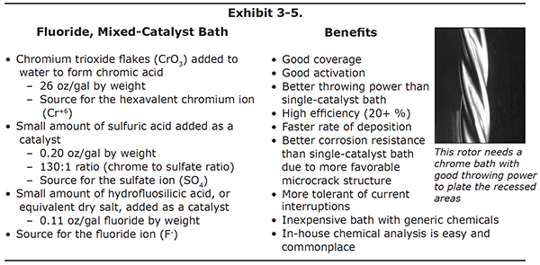
Fluoride, Mixed-Catalyst Bath
Let's turn to the next bath, the mixed-catalyst bath. Like the conventional bath, the mixedcatalyst bath contains the chromium trioxide and sulfuric acid components. However, this bath also contains fluoride ions. The fluoride is added either in the form of a liquid called hydrofluosilicic acid or as a dry acid salt (see Exhibit 3-5).
The sulfate content for this bath is less than the conventional bath. This is because the fluoride also acts as a catalyst, and the concentrations of the two have to be kept low enough, or the bath will be over-catalyzed.
As with the single-catalyst bath, the concentrations of chromic acid, sulfate and fluoride may vary for mixed-catalyst baths, as long as their ratios are held constant.
Benefits of Mixed-Catalyst Bath
The fluoride bath is much more efficient than the conventional bath, and plates at a higher rate of deposition. This saves both time and energy. It tends to cover well (i.e., good "throwing power") especially over problematic base metals where chrome plated using a single-catalyst bath might exhibit poor coverage or adhesion. For example, the mixedcatalyst bath deposits chromium with better adhesion on difficult to plate (or activate) metals such as titanium and nickel alloys. Also, mixed baths plate better into recessed areas.
Chrome deposits produced by the fluoride bath are often found to be more corrosion resistant that the deposits produced by the conventional bath. This is a result of a more favorable microcrack structure, with a higher population of thinner and shallower cracks.
Another benefit of the fluoride bath is how it responds to variations in electric power. Ideally, a plating process would always be supplied with constant, perfectly steady direct current, but in real life, the situation is not always that ideal. Current might be momentarily interrupted during plating – this can be caused by a plating rack with a loose joint, or one that is not making good, continuous contact with tank bus bars. And even if the connections are good, the power might vary because of an effect called "ripple". We'll talk more about rectifiers and ripple later in the course, but for now it's enough to note that ripple is essentially unwanted current that comes along with the direct current from the plating rectifier. The fluoride bath is much less sensitive to these changes in current flow than the conventional bath.
Although the fluoride bath, with its additional third ingredient, costs more than the conventional bath, it can still be reasonably economical to make up and maintain, since it can be made from readily available chemicals.
Disadvantages of Mixed-Catalyst Bath
Fluoride baths do have one major disadvantage, compared to the other two baths. The fluoride bath tends to chemically attack areas of the workpiece or rack that are submerged and in contact with the solution, but are not being plated. This isn't much of a problem for parts that get plated over their entire surface area. But, most parts require chrome plating on only certain regions. If the unplated regions are in contact with the fluoride chrome bath, they can be chemically etched. On complex parts that have recessed areas or crevices, even some plated areas may etch.
The damage to a part from a cathodic etch may be severe enough to ruin a part. For this reason, platers must take great care to mask all unplated areas with materials that will effectively prevent these areas from contacting the plating bath during the entire plating cycle. Typically, wax or lacquers are used for this purpose.
High-speed, Non-Etch, Proprietary Bath
The third and final bath that we will consider in detail has many of the advantages of the mixed-catalyst bath, but it does not contain fluoride. Its performance is as good as, or better than, the fluoride bath, but it does not tend to attack unprotected areas of the part, as fluoride-containing baths do. The extra components that do the trick are "proprietary," meaning that the supplier is not disclosing their identity.
Benefits of High-speed, Non-Etch, Proprietary Bath
The proprietary bath has a number of benefits. It has a high efficiency, and can plate at a fast rate, especially when operated at high power levels from the plating power supply. Tests have demonstrated excellent hardness, wearability and corrosion resistance for the deposits.
The microcrack structure of the high-speed, non-etch bath is similar to that from a fluoride bath, in that it has a high population density of thin, shallow microcracks. In fact, the microcrack count per surface area is highest for this bath under certain plating conditions. This crack structure improves corrosion resistance and spreads out deposit stresses more evenly over the deposit.
Disadvantages of High-speed, Non-Etch, Proprietary Bath
Due to its desirable deposit properties and fast speed, the bath is used extensively by original equipment manufacturers, or OEM's, with good results. However, smaller job shops can be disadvantaged by the high cost of making up and maintaining the bath. Also, the unwanted sulfate introduced during bath additions can create the need for more chemical treatments to lower the sulfate content of the bath.
Electricity and Hard Chrome Plating
Hard chrome plating is an electrochemical process. It requires chemistry as we just discussed. It also requires alternating current (AC) from the power company that must be converted to direct current (DC).
In order for the electrodeposition of hard chromium to occur, the part to be plated must be connected to the negative terminal of a direct current power supply, the lead alloy anodes must be connected to the positive terminal, and an electrical current flow must pass through the conductive chromic acid plating bath.
Remember our discussion about ions? Hexavalent chromium ions (Cr+6) are everywhere in the plating bath. To convert some of these ions to metallic chromium (Cr0) we need to "neutralize" some of them by supplying six of the negatively charged electrons (e-). Our rectifier delivers these electrons. When the rectifier is turned on, most of the electrons pass from the rectifier to the part being plated (cathode), then through the solution to the lead alloy anodes and back to the rectifier (Exhibit 3-6). However, some of the electrons combine with the Cr+6 ions at the surface of the part to form the chromium deposit.
Alternating Current (AC)
Hard chromium electroplating needs direct current or "DC" electricity in order to apply a steady negative electrical charge to the part being plated and a positive charge to its mating anode. However, electric utilities don't generate or supply DC power to their customers. They supply alternating current, or AC, instead. Power companies prefer to supply alternating current because it is easier to generate and transmit than direct current. Mechanical generators that use rotary motion, like spinning turbines powered by steam or water power, produce energy in AC form. It's also much easier to convert AC power to high voltage and low current form, which is more efficiently transmitted over long distances from power plants and then to convert it back to the lower voltage, higher current form suitable for end users at the end of the line.
So the plating shop receives its electric power supply in the form of alternating current. Before it can be used for plating, it has to be converted to direct current. To understand what's involved, let's take a closer look at alternating electricity.
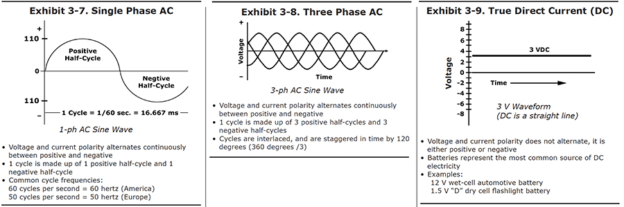
Single Phase AC
The easiest way to understand how alternating current works is to look at a graph of how the power varies with time (see Exhibit 3-7). The graph provides a picture of how the voltage changes at one of the terminals. Let's start a timer at the point marked "zero." As time increases, we move to the right on the graph. The height of the curve above each point on the baseline indicates the voltage at that time.
In this picture, we happened to start looking at the wave when the voltage was passing through zero. A short time later, the voltage has increased to a maximum. It then begins to decrease, passing through zero to negative values. After it has passed through its most negative point, it moves back to zero, and the cycle starts again. The full passage from zero, through positive values, then through negative values, and back to its starting point is called one full cycle. The positive portion is called the positive half-cycle, and the negative portion is the negative half-cycle.
In the United States, one cycle takes 1/60th of a second. Another way to express this is to say that the AC frequency for the U.S. power supply is 60 cycles per second. A unit called the "hertz" is also used -- 60 hertz means the same thing as 60 cycles per second. There is nothing magic about 60 -- most European countries generate electricity with a frequency of 50 hertz.
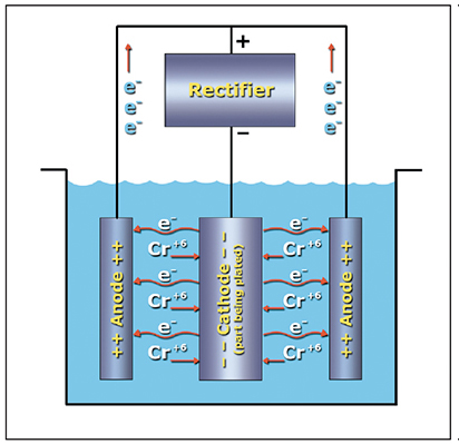 |
| Exhibit 3-6. Hard chrome plating electrochemistry diagram. |
Three Phase AC
Now it gets a little more complicated. The more power electric wires carry, the thicker the wires have to be. Large industrial loads would require impractically large wires. It turns out to be more efficient to supply electricity in large amounts by using a system that provides three feed wires, rather than two. You can use smaller wires, and you can avoid also some of the power loss that is caused by magnetic fields that build up around wires whenever they carry alternating current.
If you measured the voltage being supplied by any one of those wires, it would look like the simple wave in Exhibit 3-7. But the three wire systems are set up so that the voltages do not peak at the same time. The graph on Exhibit 3-8 shows the voltages of each of the three wires, all drawn on the same graph. As you can see, the peaks take turns. The second wire passes through its positive peak when the first wire is one-third of the way through its cycle, and the third wire peaks when the first wire is two-thirds of the way through.
This system is called three phase AC. In the United States, three-phase electricity, at a voltage of 440 volts, is the type of power most commonly supplied to industrial buildings.
True Direct Current (DC) (Battery)
The kind of power we want for plating has a much simpler graph, like the one shown in Exhibit 3-9. It's what you would get from a battery. The voltage never changes sign, unless you disconnect the wires to the battery terminals, and reverse them.
Rectified Direct Current (DC)
How can you get direct current from the alternating current supplied by the electric company? One way to convert AC to DC would be to hire a worker who would stand next to the electric mains, and watch an electric meter. Whenever the voltage changed from positive to negative, the worker would disconnect the wires, switch them around, and reconnect them. When the voltage swung back to positive, he would reverse the wires again. He would have to work fast, though, since he would have to reverse the wires 120 times each second.
Fortunately, it is possible to build an electronic switch that essentially does the same thing. It's a device called a recitifier. It depends on a solid state component called a thyristor that essentially acts like a one-way valve – it will only let current pass in one direction. The rectifier keeps the current from flowing the wrong way, and stripping off the metal you are trying to plate.
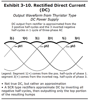
So that's progress. But note that it is still not true direct current. The waveform doesn't look like the horizontal line that you would get from a battery. As you see in Exhibit 3-10, rectified DC is an approximation of true DC. The output waveform looks like a series of humps, all connected together, forming a bumpy-looking horizontal line. Each of the humps is derived from either the top of the three positive halfcycles, or the inverted bottoms of the negative half-cycles. The rectified DC is not a single, constant voltage. Instead, it is a voltage of the same polarity, but one which fluctuates, or "ripples". But with a three phase supply and a good rectifier, the fluctuations are small enough that they are acceptable for chrome plating operations.
Power Supplies Used For Hard Chrome Plating Systems
Several different types of DC power supplies are used for hard chrome plating. The earliest units were simply DC generators attached to AC electric motors. With the advancements in semiconductors, especially those that could handle high current loads, these were replaced by solid state units.
Silicon Controlled Rectifiers (SCRs) are still popular where remote controls and automation are needed, as well as tap switch units when these features are not required. The variable powerstats have been used largely for applications that don't require high current outputs. It's easy to find a 15,000 ampere by 9 volt DC SCR rectifier, but not a variable powerstat.
Highly efficient, programmable switch mode power supplies have evolved that are very small in physical size, compared the other designs.
Let's talk a little about the differences between the most common types of these power supplies:
- Common
- Variable powerstat (manual and motorized)
- Tap Switch
- SCR (silicon controlled rectifier)
- New technology
- Switch Mode
- Uncommon / obsolete
- Saturable-core reactor
- Motor generator
Variable Powerstat
Variable powerstat units (Exhibit 3-11) usually have a single rotary switch to control the output. This switch is coupled to a mechanism on the primary transformer that changes the ratio of the primary winding to its secondary winding. This design allowed the user to adjust the output to any desired voltage, within the range of the unit.
As the units get larger, the rotary switch for manual units gets larger also, and harder to turn. At some point, it makes sense to place a motor drive on the transformer, to adjust the winding ratio, and have a small rotary potentiometer control it. This represents the motorized variable transformer design. However, even the motorized variable powerstats can't be built to deliver the very high DC current outputs of the SCR type power supplies that will be discussed later in this section.
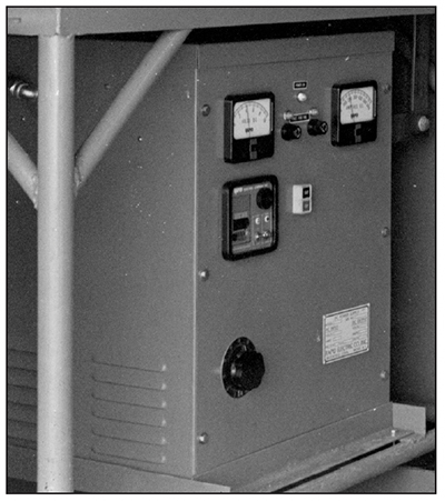 |
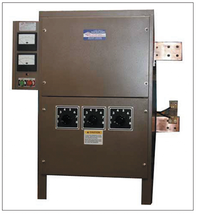 |
| Exhibit 3-11. VARIABLE POWERSTAT: DC output voltage is adjusted by rotating the black knob in the lower left area of the rectifier cabinet | Exhibit 3-12. Tap switch rectifier. Courtesy of Darrah Electric Co.) |
Tap Switch Rectifier
The tap switch rectifier (Exhibit 3-12) incorporates a simple way to regulate DC output that provides only voltage control. The main transformer in the units has a series of taps for its input or primary copper windings. There are three rotary switches on the rectifier cabinet – one for each of the three AC phases – that are connected to these winding taps. By using the tap switches and transformer taps, the AC current to the transformer is directed through a different number of primary windings, which varies the current in the output windings proportionally.
The operator adjusts the DC voltage output of the rectifier by using the tap switches, being careful to balance the phases by keeping all three within one "click" of the others. For example, if the output happened to be 4.4 volts DC when all three taps were at position "4," and the operator wanted 7.6 volts, he would raise tap switch number one to position 5, then switch 2 to position 5, then switch 3 to position 5, then switch 1 to position 6 – and so on – until the DC voltage output was as close as possible to 7.6 volts.
It's unlikely that the operator would actually get exactly 7.6 volts. This is because the voltage regulation from a tap switch rectifier is "stepped," rather than continuous. Each time you rotate a knob one position, the next transformer tap is selected, and the output voltage is stepped up or down by a fraction of a volt. Tap switch rectifiers usually supply eight-position switches, with 24 possible voltage outputs (3 x 8 = 24).
Although the stepped output and lack of constant current regulation are negative factors, the tap switch design has several benefits, including low purchase cost, efficient AC power use and a DC output that is favorable for hard chrome.
Tap switch rectifiers are usually placed close to its process tank, so that the operator can work the controls located on the cabinet. Although uncommon, some of these units have been fitted with a remote control capability.
Since electronic reversibility is not possible, external reversing switches are used if the tap switch power supply needs a polarity reversing capability. These reversing switches can get quite large and contain a lot of copper. One popular rotary design works on a cam-andlever principle, and is manually operated. Other designs use air pressure to activate the switch and maintain the required high pressure between the copper contact blocks.
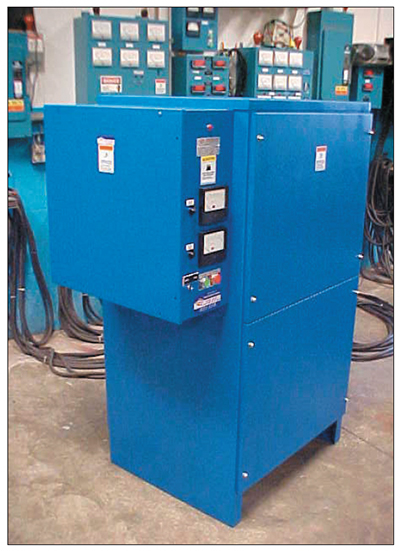 |
 |
| Exhibit 3-13. SCR RECTIFIER: Controls are mounted on the cabinet. Courtesy of Darrah Electric Co. | Exhibit 3-14. Switch mode rectifier with touch pad interface. |
Silicon Controlled Rectifier (SCR)
The term "Silicon Controlled Rectifier", or SCR for short, is a bit confusing, because it really describes a semiconductor component in the DC power supply which is also known as a power thyristor. Since platers often refer to their power supplies as rectifiers, these units are often called "SCR rectifiers" (Exhibit 3-13).
The SCR or power thyristor was an engineering breakthrough, because it allowed very high amperage to be regulated by only milliamperes of control current. You can think of these devices as large, switched diodes, that allow current to flow in only one direction, and only when switched on by the milliampere gate signal. In order to adjust the power supply's DC output, the control circuitry varies the percentage of time that the SCR's are gated open. This millisecond time-slicing has an unwanted effect, as it can result in an interrupted waveform unsuited for a chrome plating process that doesn't like any sort of current interruption. In order to overcome this problem, SCR units specified for chrome plating add ripple filtration components to attenuate the output. Ripple and ripple filtration are discussed later in the course.
SCR power supplies are all electronic, having no moving parts except for the exhaust fans fitted to air-cooled units. They can be designed to be electronically reversible, which is useful for the reverse-etch activation procedure prior to chrome plating. They also have a rich set of control features. For example, the circuitry that regulates DC output can be selected by the operator to hold either the voltage or the current constant during long plating cycles. Hard chrome platers will usually use the constant-current mode, so that the plating rate of deposition will stay as steady as possible. However, some platers like to control chrome plating by voltage. We will discuss both current and voltage control later in the course.
SCR type rectifiers usually have remote control cabinets. This allows the main power supply to be placed in an equipment room or other location away from the plating tank. The plater still has convenient access to the voltmeter, ammeter and control switches located in the small remote cabinets sited near the plating tank.
SCR type rectifiers are not as electrically efficient as tap switch units.
Switch Mode Power Supply
Switch mode power supplies are the newest and most exciting power supplies available for the metal finishing industry. The fact that they have very low ripple, typically less than 1%, makes them particularly well suited for hard chrome plating.
DC voltage output is regulated by high frequency switches that repeatedly connect and disconnect the power handling components within the unit to both the AC input and DC output. The units are highly programmable, electronically reversible and can be operated in constant voltage or constant current modes. The small physical size and low weight of the units and their internal components is a direct result of the high frequencies at which they operate. Many of the units are so small that they can be wall mounted (Exhibit 3-14).
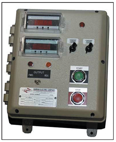
Exhibit 3-15. Rectifier remote controls. Courtesy of Darrah Electric Co.
Factors in Choosing a Power Supply for Hard Chromium Plating
What kinds of factors need to be considered when selecting a power supply for hard chrome plating?
First of all, the unit must satisfy the DC voltage and current needs for the process. Large parts, and tanks with many parts, translate into a large surface area that must be plated at once, and thus a large amperage requirement. A quick rule of thumb would be to take the total square inches of surface area, then multiply by the current density to be used, in amperes per square inch. For example, if 2,500 square inches are to be plated at 3 amps per square inch, the power supply must provide at least 7,500 amps DC. If all parts are plated using conforming anodes with close anodeto- cathode spacing, a 0 to 9 V rectifier may suffice. But if stick anodes are used, a 0 to 12 V unit may be needed. This requirement will be explained in more detail in Section 4.
Location is an important consideration also. If the power supply is placed in another room, or very far from the chrome plating tank, then some sort of remote control capability is needed (see Exhibit 3-15). This would encourage the use of a SCR or switch mode power supply. Variable powerstat and tap switch units are better when sited near the tank, so that the operator can access the gages and switches on the rectifier cabinet.
The chrome plating of some parts, especially original equipment plated in quantity, may lend itself to a more automated control system design for the power supply. For example, an SCR or switch mode power supply may be configured to reverse etch activate a part at 5 V and 1,000 amperes for 30 seconds using reverse current, pause, change to forward polarity, ramp the plating current up from 500 amps to 2,000 amps over 90 seconds, plate the part at 2,000 amps for 4,500 amperehours, then shut itself off.
Ripple can be thought of as the small amount of the original alternating current that is superimposed on the output DC waveform. Electrocleaning and electrostripping processes can tolerate a significant amount of ripple, but chrome plating cannot. The adhesion of the chrome to its base metal, and even properties of the electrodeposited chromium itself, can be adversely affected by high ripple. A common rule-of-thumb often states that ripple should not exceed 5% for hard chrome plating. However, percentages around 1% or less are much better. Switch mode power supplies have inherently low ripple and are well suited. On the other extreme, SCR power supplies have very high ripple, especially when operated at the low end of their DC voltage and amperage capacity, and always need the addition of large and expensive ripple filtration circuitry. Tap switch units are in the middle somewhere. Ripple can be easily measured, and is discussed later in this course.
Rectifier efficiency is a big issue. Less efficient units consume more electrical power and create more waste heat that must be removed by cooling systems. The 85% or so efficiency of a large SCR unit can translate into a large cooling requirement. Switch mode units are typically at least 90% efficient, and tap switch units around 96%.
Air Cooling vs. Water Cooling for Power Supplies
Since the rectification of AC to DC is not 100% efficient, all rectifiers produce heat. Power supplies remove this heat using air or water cooling systems.
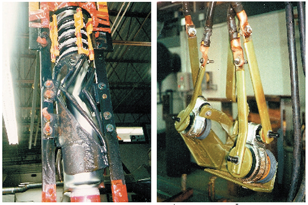
Air cooling is the simplest method (Exhibit 3-16). Room air is sucked in one end of the cabinet, and exhausted out the other. Heat removed from the power supply is transferred to the plating room environment. This might be a good thing in colder, winter climates, but in warm climates it can raise the temperature of a shop that is already uncomfortably hot. Manufacturers have improved fan blade designs, but the larger units can still be noisy. In the early years of plating, many air-cooled rectifiers were damaged by process fumes (Exhibit 3-17). However, exhaust ventilation systems installed in plating shops have improved so much that rectifier corrosion by process fumes is no longer much of a problem.
 |
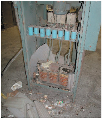 |
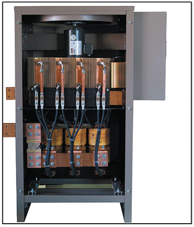
| Exhibit 3-16. Air-cooled rectifier. Courtesy of Darrah Electric Co. | Exhibit 3-17. Air cooled rectifier debris. |
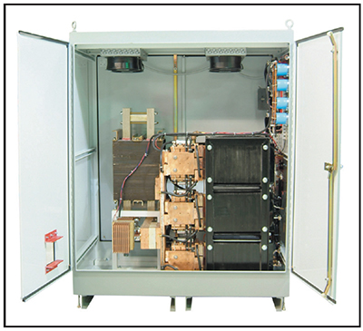
Water cooled rectifiers (Exhibit 3-18) can have two types of heat exchangers: fluid-to-air or fluid-to-fluid. Fluid-to-air heat exchangers are often called "radiators". In your automobile, hot fluid from the engine block is directed through multiple, finned passageways in a metallic radiator. When the fan kicks on, the airflow over the outside of the fins exchanges the heat from the fluid to the air. This is the way that a water-cooled rectifier that uses a radiator works. Fluid is recirculated through components in the unit that generated heat, and the radiator that removes it. Note that, in warmer climates, the heat exchanged to a warm room can make it even more uncomfortable. The advantage to this type of system, compared to the air-cooled system, is that the recirculated fluid is more efficient at extracting heat and conveying it away from the hot components.
With fluid-to-fluid cooling (Exhibit 3-19), the heat exchanger is designed so that heat is exchanged between two fluids that differ in temperature. On the one side of the exchanger, fluid is recirculated through components in the unit that generated heat, just like the previous example. Cool water from a chiller or cooling tower circulates through the other side of the heat exchanger, and conveys the heat to a remote location.
Power supplies that incorporate fluid-to-fluid cooling have many advantages. Without the need of exhaust fans, they are quiet. They can be built in smaller cabinet sizes, and the cabinets can be sealed to prevent atmospheric corrosion. This efficient design has a couple of drawbacks though: it's more expensive, and fluid leaks represent a significant problem.
 |
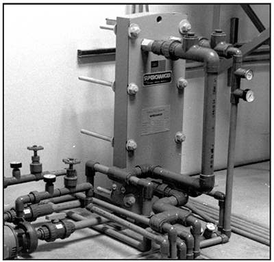 |
| Exhibit 3-18. Water-cooled rectifier. Courtesy of Darrah Electric Co. | Exhibit 3-19. FLUID-TO-FLUID HEAT EXCHANGER: Cooling tower water is used to cool water that is recirculated through rectifiers |
Rectifier Bussing and Tank Bus Bars
Chromium electroplating is a low-voltage, highamperage process. The DC voltage range is quite low: from 3.8 V to perhaps 12 V on the high end. However, when large parts are plated at a current density of 1 to 4 amps per square inch, the amperage can get quite high. For example, a large roll with 5,000 square inches plated at 2 amps per square inch requires 10,000 amps!
It takes a lot of bussing to convey this high amperage from the power supply to the plating tank, and there will still be some power losses along the way. Due to the high cost of copper, most runs will be specified at one inch of copper cross section per every 1,000 amps to be carried. As an example, if the rectifier has a 3,000 amp capacity, the positive and negative bus runs will each need 3 laminations of 1⁄4 in. x 4 in. copper to meet the 1 square inch per 1,000 amp requirement. This is a minimum requirement. In shops where the rectifier is located more than 20 feet from the tank, a greater cross section of copper is needed due to electricity transmission losses.
Chrome plating is disadvantaged by its low voltage, because any resistance in the circuit translates into significant current losses. Resistance can occur for example at the junction where copper bussing is bolted together. Therefore, the chrome plating shop must size the bussing properly, and also keep all joints or contact areas clean and corrosion free, in order to minimize losses due to excess electrical resistance. Excessive electrical resistance will cause heating of the connections. In extreme cases, connectors can get sufficiently hot to cause severe burns or even fires.
Racks of parts and anodes do not connect directly to the rectifier bussing. Instead, tank bus bars are permanently installed on the chrome plating tank. The tank bus bars serve as a contact platform to physically support the weight of the parts, racks and anodes, and also to transfer the DC power from the bussing to them. Although many custom designs are utilized, a couple of tank bus bars designs are common. These are discussed next.
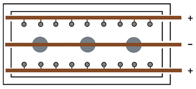 |
| Exhibit 3-20. Diagram shows 3 parts and 18 stick anodes. Stick anodes are usually left in tank when parts are removed. (+) pole = Anodes; (-) pole = Parts |
3 Bus Bar Design
The traditional names for two popular tank layouts are: the 3 bus-bar system and the 2 bus-bar system. These names are confusing, because the bars mentioned are tank bus bars, and have nothing to do with the copper bussing that runs from the rectifier to the tank. However, for the sake remaining consistent with the names used by platers, we'll use them here.
With the 3 bus bar system (Exhibit 3-20), stick anodes are hung from the two anode bars near opposite sides of the tank and the parts are hung on the center bar. This places the anodes on both sides of the parts to be plated. Typically, the stick anodes remain in the tank at all times, although some shops remove them if there will be an extended idle period.
This is done to prevent the anodes from going passive, a condition that will be discussed later in the course.
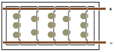
Exhibit 3-21. The five reversible racks have both anode and cathode members. Multiple parts and anodes may be mounted on the same rack. (+) pole = Anodes; (-) pole = Parts.
2 Bus Bar Design
The 2 bus bar system (Exhibits 3-21 and 3-22) has its negative tank bus bar along one rim of the tank, and the positive along the opposite rim. When a tank is set up for standardized reversible racks, the spacing of the tank top bars is set to match the distance of the anode and cathode hooks for the racks. After the parts and their conforming anodes are assembled on a reversible rack, it is placed in the tank in the reverse polarity direction, so that during the brief reverse etch activation procedure, the lead anode will be attached to the negative tank top bar and the part to be plated attached to the positive bar. After the etch, the rack is lifted a few inches, spun around 180 degrees, then dropped back in the tank for the duration of the plating cycle.
It's important to note that any other racks can remain plating during the time when this rack of parts was reverse etched. The rectifier feeding the plating tank doesn't even need a reversing capability.
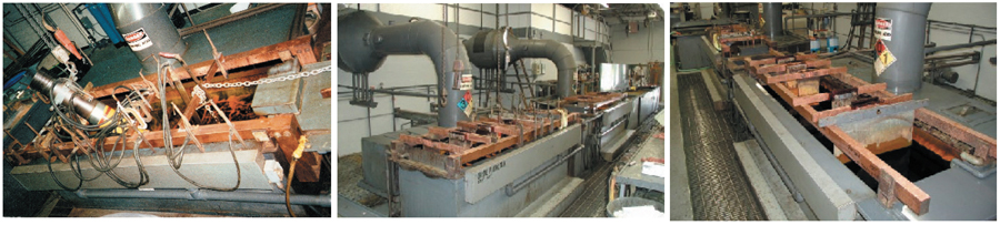
Exhibit 3-22. Various 2 bus bar pictures.
It's possible to utilize a 2 bus bar tank for plating parts without reversible racks. This is done by using crossbars that have an electrical insulator under one end. In this scenario, it is beneficial to have a DC power supply with reversing capability.
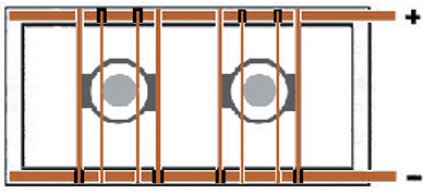
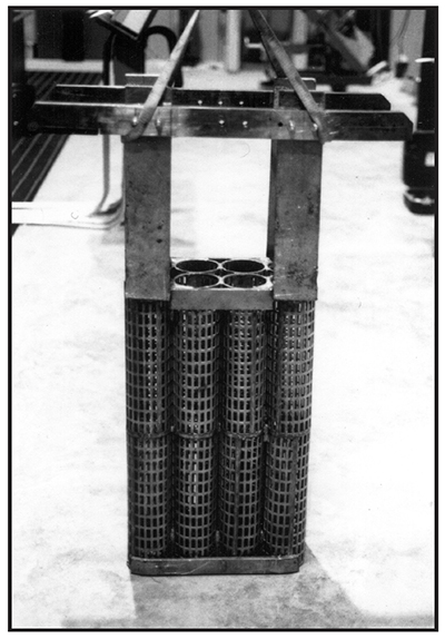
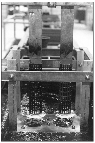
Exhibit 3-23. Two cylinders plated inside cylindrically-shaped conforming anodes. Copper crossbars have insulators under one end in order to prevent short-circuiting. (+) pole = Anodes; (-) pole = Parts.
Consider a 3 in. diameter steel hydraulic rod that is to be plated inside of an 8 in. diameter, cylindrically-shaped conforming anode. The anode is built with two vertical leads, so two horizontal copper crossbars are attached (Exhibit 3-23). The crossbars are placed so that their electrical insulators (black blocks), on one end, are facing downward and are both on the same end of the anode. The anode is lowered into the plating tank first. If the rectifier is reversible, the anode is placed so that its copper crossbars connect to the positive tank bus bar, and the insulators prevent electrical contact with the negative tank bus bar. The rod to be plated has a fixture with a vertical lead, with its own copper crossbar. When it is lowered into the plating tank, the crossbar must make electrical contact with the negative tank top copper, and its insulator must prevent contact with the positive bar. If no other parts are in the tank, or if others are to be started also at this time, the rectifier is set to apply reverse polarity to the bus for the etch cycle, then normal or forward polarity for the duration of the plating cycle.
If the rectifier does not have a polarityreversing capability, it is still possible to accomplish both reverse etch and plating procedures using the rod and anode situation just described. The operator first places the conforming anode assembly in the tank so that its crossbars connect to the negative tank top bar. The rod is placed in the center, with its crossbar connecting to the positive bar. The part is reverse etched as needed. Then, both the anode assembly and the fixtured part must be rotated 180 degrees so that the anode crossbars now connect with the positive tank top bar, and the part connects with the negative one.
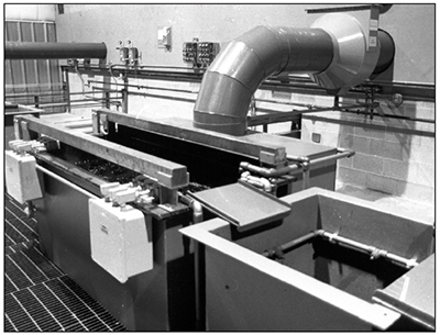
The hard chrome plating tank shown in Exhibit 3-24 has two square bus bars mounted directly over the front and back rims of the tank. It is set up for use with anode and cathode crossbars.
The process fumes are exhausted beneath the rear bus bar, into the exhaust hood. This is a better design than having the hood slots above the bus bar, because it minimizes the erosion of the copper bar by the chromic acid mist.
Instead of being placed flat, bus bars are sometimes placed on edge. This design can increase the contact area for the rack as shown in Exhibit 3-25.
 |
 |
|
Exhibit 3-24. 2 BUS BAR DESIGN FOR CROSSBARS: This tank has the positive bus bar over the back rim, and the negative bar over the front rim. |
Exhibit 3-25. A tank bus bar placed on edge and a rack hook designed for optimal contact with the tank bus bar. |
Tanks
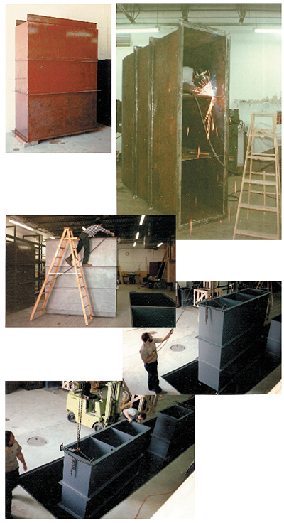
Exhibit 3-26. Tank pictures, including fabrication and installation
Hard chrome plating is a tank process. The vessels used must be strong enough to overcome all the physical, mechanical and chemical forces applied to them, for long periods of time. This is no easy task, especially for large or deep tanks filled with aggressive, hazardous or toxic chemicals.
Process tanks for hard chrome plating lines should always be designed and specified by qualified engineers, or by tank fabrication companies with years of experience with hard chrome systems. Tank failures that result in leakage can have significant monetary and environmental consequences, especially if secondary containment systems also fail or are not present.
It would be unusual to have only a hard chrome plating tank, all by itself. Normally, various cleaning, stripping and rinsing tanks would accompany the plating tank in the process line. Process tanks are usually arranged in order of use, so that the plating operator can transfer parts efficiently from process to process (i.e., good "workflow").
The best tanks for hard chrome plating lines are steel tanks that are painted on the outside, and coated or lined on the inside. The steel provides the structural strength, and the coating or lining systems provide the chemical and electrical barrier.
1/4 in. steel plate is popular for small and medium tanks, but larger ones need thicker plate. Tanks generally need a substantial top rim, because heaters, heat exchangers, pumps, filters and other equipment may be bolted to the rims. One of the biggest challenges for large or deep tanks is to prevent bulging. Process fluids and rinse water exert enough outward force to bulge a tank unless adequate structural supports are added to prevent this. Typically, the girth supports are arranged as a series of horizontal bands around the outside of a tank, spaced close together enough to prevent bulging.
Some parts, like large steel rolls or rotors, are too heavy to be supported by the tank rims. In this case, the tanks are placed inside of an outer steel superstructure that supports the heavy weight during processing.
Chrome tanks lose heat from the sides of the tank as well as the surface. Some shops insulate tanks to reduce their use of energy and save money.
Lets talk about some of the construction differences between plating, rinsing, stripping and cleaning tanks.
Chrome Plating Tanks
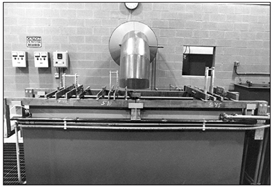
Exhibit 3-27. This hard chrome plating tank is set up for plating a group of parts on the left side from one rectifier, and another set of parts on the right side using a second DC power supply. This arrangement is advantageous when the parts differ in size and shape, because you can have two distinct voltages and currents. REAR WALL: Rectifier, heating and cooling controls; LEFT SIDE OF TANK: Fed by 1st rectifier; RIGHT SIDE OF TANK: Fed by 2nd rectifier (Rectifiers are in back room).
Hard chrome plating tanks (Exhibit 3-27) are the most demanding of all the tanks in the plating line. The tank holds a strong, oxidizing acid with a low pH. The chromic acid is highly corrosive in both its liquid form, and also the mist that escapes from the surface during plating.
Since the electroplating process requires a high current to the workpiece, a lot of heavy tank bus bars may set on the top rim. The racks and parts may be heavy, and the lead anodes surely are. Electric heaters, heating and cooling coils, pumps and filters may be mounted on the rim. Most plating tanks will have the exhaust ventilation hood pressing down on the back rim, and may also have a push-air hood on the front rim. All of these items add to the already heavy steel tank and plating solution.
Once the steel tank has been fabricated, it is grit-blasted, then painted and lined. Early chrome tanks were lined with sheet lead, with all the seams welded. These tanks usually enjoyed the longest life expectancy of any lining system, perhaps 15 years or more, but had a couple of disadvantages. They were heavy, and the tank walls were electrically conductive, which could cause stray currents in the tank to interfere with the plating current to the workpiece. In order to overcome this effect, and to protect the soft lead from being scraped and gouged when handling racks and anodes, the tanks could be lined from bottom to top with acid-resistant bricks. Also, there are not many expert "lead burners" left in the world who can properly weld leak-proof seams in the sheet lead.
Rigid plastic liners, fabricated by welding plastic sheets together, have not held up well in heated chrome tanks. The point of failure is usually near welds, where the plastic suffers from a phenomenon known as "stress corrosion cracking."
Modern chrome tanks are often Koroseal© lined. This is a plasticized polyvinyl chloride polymer first commercialized by B.F. Goodrich Co. around 1930. After grit-blasting and priming the steel, the flexible Koroseal lining material is affixed to the inside tank walls and top rim using a high-temperature contact adhesive. The seams are thermally welded and covered using strips made of the same material, to form a leak-tight lining system. The material withstands chromic acid up to about 140 degrees Fahrenheit or so, and lasts about 4-7 years under normal use. This lining material is attacked more quickly by the airborne chromic acid mist immediately above the liquid surface. In order to counteract this tendency, an overlay, sometimes called a "skirt," is added to the top foot or so. When the outer material has been compromised by the oxidation from the mist, the inner layer is still intact for a while longer.
As an alternative to the bonded liner, or as a repair technique when the bonded liner fails, flexible drop-in liners may be used. These are sometimes referred to as bag liners. It is important that the flexible liner fits the inside of the tank properly. If it is too small, it may stretch and tear. If it is too large, excess material may protrude into the space occupied by the anodes and racks.
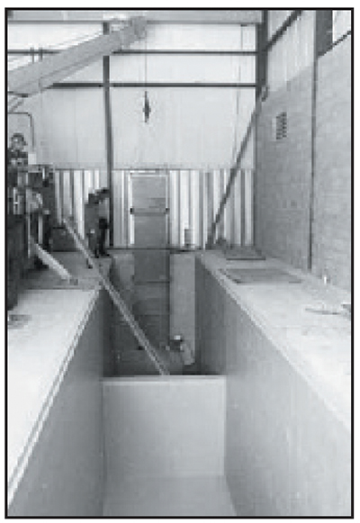
Exhibit 3-28. SECONDARY CONTAINMENT PIT: Deep tank is lowered into a reinforced concrete pit that has been painted with a chemical resistant coating. Pit has knee wall to separate acid from alkaline tanks.
In order to avoid leaks, submerged plumbing fittings are almost never fitted to chrome tanks.
The width, length, and depth of hard chrome tanks are influenced mainly by the sizes and number of parts being plated, the types of racks and fixtures used, and the available shop space. Typically tanks are three to four feet wide and up to 12 feet long (much longer tanks are used for plating printing rolls and similarly sized parts). Common tank depths range from 3 to 12 feet (much deeper tanks are also in use for plating special parts). Shops with deep tanks must have available space below the plating room floor to accommodate the lower part of the tank and a sufficiently high ceiling height to raise the part and lower it into the tank. Tank height must also take into account the necessary "freeboard" height (distance between the solution and the tank lip). Freeboard is needed to accommodate changes in solution height when large parts are plated (i.e., displace solution causing an increase in solution height). Freeboard is also needed for efficient operation of the air exhaust system, which is discussed later in this section.
Hard chrome tanks are typically oriented with their length parallel to the aisle way (see previous pictures of hard chrome tanks in this section). This permits platers to have full access to the length of the tank, which is needed for most plating operations, such as fixturing, moving anodes, cleaning bus bars, etc.
Environmental Releases of Chromium from Plating Tanks
Releases of chromium-bearing liquids are of great concern, and can have an immediate and catastrophic effect on the environment. Chrome plating tanks are often large in volume, and contain high concentrations of hexavalent chromium. There should be three containment barriers between the plating bath and the ground and groundwater beneath the building.
The first barrier is the tank lining system in the chrome plating tank. These bonded or drop-in liners will ultimately fail, and when they do, chromic acid will get behind them and corrode the steel tank walls or welds. Chrome tanks should be drained and inspected annually, as an attempt to spot the lining failure before it occurs.
The second barrier is the steel tank itself, which serves as the containment vessel for the plating bath. The exterior surfaces of chrome plating tanks should be visually examined weekly, for evidence of corrosion or leaks.
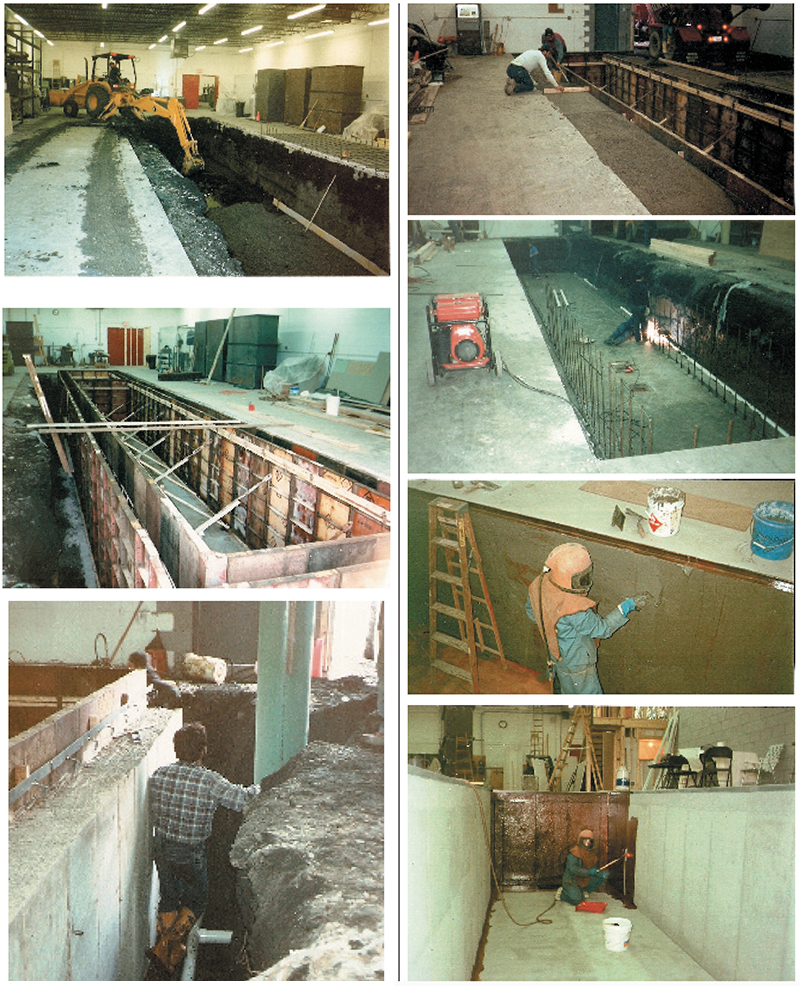
Exhibit 3-29. Containment area pictures, including construction.
The third barrier is the secondary containment pit that was designed and built to contain process spills or leaks (Exhibit 3-28). A good containment pit will be made from thick, steel-reinforced concrete, then coated with a suitable, high-quality chemical resistant coating. In the event that the plating tank ruptures or is overflowed, all hazardous liquid should be contained in the pit until it can be pumped out. It's a good practice to divide the containment pit into separate compartments that segregate process chemicals. For example, one compartment would contain the overflow or leak from an alkaline strip tank, another compartment would hold chromic acid from the plating tank, and so on. With this design, it may be possible to filter the fluid from the pit and return it to the process tank of origin.
Tank overflows occur much more frequently than tank ruptures. For example, a plater can easily overflow a plating tank if a garden hose is used to raise its liquid level. It doesn't take much for the plater to be distracted by other tasks, and forget about the running hose. For this reason, any manual refill system should have a spring-loaded valve that requires the operator to hold the valve open, and shuts off automatically when the operator lets go of the valve handle. Automated refill systems can work well, but should have redundant liquid level sensors and solenoid valves. In case one liquid level sensor should fail, the second one, wired in parallel, should signal the valves to stop fluid flow. Two solenoid valves placed one-after-the-other can prevent a tank overflow if either fails to close properly. Incomplete valve closure occurs frequently when foreign particles become trapped or lodged in the valve seat.
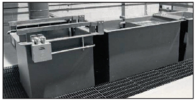
Exhibit 3-30. This photo shows an alkaline electrostrip tank at left, followed by a doublecounterflow rinse tank. Both copper bus bars are attached to the positive pole of the rectifier. The tank itself is attached to the negative pole.
When chromic acid is introduced into the ground or groundwater, it doesn't stay in a localized area. Rather, the water-soluble chromium will migrate into water tables or other aquifers, causing damage over a wide area. Typically, such a release requires expensive remedial cleanup operations that can last months or longer.
Exhibit 3-29 consists of containment area pictures, including construction.
Alkaline Electrostrip Tanks
Any shop that plates chromium will probably want to strip it.
The most common tank for this purpose is called an alkaline electrostrip tank (Exhibit 3-30). The tank is usually filled with a solution of sodium hydroxide, a mixture of sodium hydroxide and sodium carbonate or a proprietary alkaline stripping solution that will most likely contain these compounds. Steel tanks work the best. Although the exterior surfaces are coated for protection from dripped chemicals, the interior is left intentionally unpainted. There is a reason for this. The tank itself is attached to the negative pole of the stripping power supply. The part to be stripped is made positive. The bare tank walls serve as the cathode electrode in the electrostripping process in most operations, however, customized conforming steel stripping cathodes are also used. The customized tools provide close anode to cathode spacing and reduce stripping time by 75 percent.
As with any process tank, it must be sized and built to handle its own weight, the liquid within and any parts and racks bearing on it during the stripping cycle.
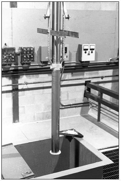
Exhibit 3-31. SCRUB TANK: Parts are handscrubbed with wet cleanser or pumice on an abrasive pad. The empty tank is pumped dry when rinse water gets too high.
Scrub / Clean / Electroclean Tanks
Although parts can be cleaned by other methods, many hard chrome plating lines will have simple hand scrub tanks, or aqueous alkaline cleaning tanks that may or may not involve the use of a direct current power supply. When no power supply is used, the tank is called an alkaline cleaning tank. When the power supply is used to assist the cleaning process, the tank is called an alkaline electrocleaning tank.
One very effective way to clean parts is to hand scrub them with wet pumice or nonchlorinated cleanser using an abrasive pad.
This simple setup only requires an empty tank and water hose (Exhibit 3-31).
Although it would be possible to blend your own cleaning solutions from basic chemicals, nearly all shops that use aqueous alkaline cleaning or electrocleaning tanks purchase proprietary cleaners.
Again, steel tanks work the best. The exterior surfaces are coated for protection from dripped chemicals, and the interior may either be coated or left intentionally unpainted if the tank walls serve as an electrode for either anodic or cathodic electrocleaning.
It must be sized and built to handle its own weight, the contained liquid and any parts supported during the cleaning cycle.
Rinse Tanks
Multiple rinse tanks are a necessary component of any waste minimization strategy for a chrome plating facility that wants to reduce or eliminate chrome bearing liquid waste (Exhibit 3-32). This concept will be discussed later in the course.
Rinse tanks contain diluted chemicals, so the chemical resistant coatings hold up over time. And, since they are not electrified, they don't have to carry the weight of heavy copper bussing. Heated rinses will have immersion heaters or heating coils, and should have exhaust ventilation to carry away hot water vapor.
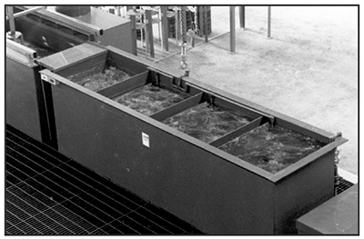
Exhibit 3-32. 4-BAY COUNTERFLOW RINSE TANK: High dragout rates may require 4 or more bays to maintain a clean final rinse bay.
Rinse tanks often have multiple bays with dividing baffles that allow clean rinse water to travel through the bays in
a direction that is opposite to the direction that parts are rinsed.
These are called "counterflow" rinses. If it is a three-bay rinse tank, and parts are rinsed from left to
right, then clean makeup water is
flowed from right to left. The leftmost, mostconcentrated
bay is pumped to the plating tank to replace evaporative losses there. Spray rinse tanks can be used to rinse parts
with a minimum amount of fluid. When they are positioned immediately after the plating tank, the source fluid for
the footswitchcontrolled spray nozzles can be rinse water from the next immersion rinse bay.
Anodes
Hard chrome plating is an electrolytic process that relies on the flow of electricity between two submerged electrodes of opposite polarity, anodes and cathodes.
The part to be plated is referred to as the "cathode" electrode, because it's connected to the negative pole of the DC power supply during the plating cycle. The other electrode is attached to the positive pole during plating, and platers refer to these anodic electrodes as "anodes".
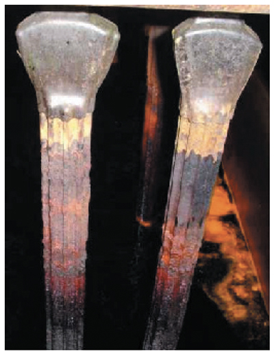
Exhibit 3-33. STICK ANODES: 2 in. diameter, fluted anodes. (Note: Used lead anodes are covered with toxic heavy metal and should not be handled without gloves.)
Anodes must be fabricated from materials that will not readily decompose when subjected to aggressive chromic acid and the positive electrical polarity. Lead holds up pretty well in this harsh environment, and it is material of choice for almost all chromium plating. However, pure lead is too soft to maintain its shape and therefore, a small percentage of antimony or tin is added to stiffen up the metal, typically in the range of 4 to 7 percent. Antimonial lead anodes work well for conventional chrome baths (chromic-sulfuric only), but they decompose quickly when used in the fluoride baths. The tin lead anodes work best with fluoride and proprietary high-speed, non-etch baths.
Lead has some drawbacks when used for hard chrome plating. It has a low melting point, and doesn't conduct electricity very well. Although the submerged portions of anodes are actually cooled by contact with the plating solution, the attachment leads are above liquid. If these attachment leads carry too much current for their cross-sectional area, they can heat up to the point that they soften and drop the heavy anode into the tank. Anodes for high-current applications should always have lead-clad, copper-cored attachment leads. Copper carries about 8 times as much amperage as lead per cross-sectional area. When anodes are long, it's a good idea to have the copper-core extend farther down the anode, all the way to the bottom if practical.
Stick Anodes
Stick anodes are cylindrically-shaped anodes, usually 1-1/2 in. to 2 in. diameter, of various lengths. 3-buss-bar plating tanks will have the stick anodes hanging from the two outside tanktop copper bars, located near opposite rims of the tank. 2-buss-bar tanks can use stick anodes also, if they are hung from either crossbars or circular or polygonal-shaped fixtures designed to space them equally around a part to be plated.
The trouble with stick anodes is that they are usually positioned too far away from the workpiece. The anode-to-cathode spacing can be 6–12 in. or more. The voltage required to plate a part at a certain amperage increases as the anode to cathode spacing increases. For example, a part with 1,000 square inches plated at a current density of 2 amps per square inch requires 2,000 amperes. It might only need 4.4 V to get the 2,000 amps with a 3⁄4 in. anode spacing, but might need 8 to 12 V to pull the same 2,000 amps with 12-14 in. spacing.
Conforming Anodes
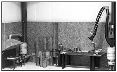
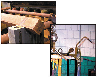
Exhibit 3-34. ANODE CASTING (left side) ANODE WELDING (right side).
A better way to plate is to use conforming anodes. As the name implies, conforming anodes are generally built to match the shape of the area to be plated, and to be closer to it. Properly sized and shaped conforming anodes can offset the tendency of chromium to deposit thicker on the ends of parts, and can also be more effective than stick anodes in depositing chrome into recessed area of parts. Small parts can have conforming anodes that are only a half inch from the workpiece. Larger shafts, cylinders or rolls might have an anode-to-cathode spacing of a couple of inches. Unlike stick anodes that come in standard sizes, conforming anodes are either built in-house or ordered to specification.
It takes a skilled and experienced craftsman to cast, cut, shape and weld lead. The welding of lead is called "lead burning." It's difficult, because the torch must heat small, localized regions to a molten state in order to fuse the lead together, but can't allow the adjacent lead regions to melt. Good exhaust ventilation and air pollution control systems are mandatory for the lead casting and burning stations, in order to avoid the many adverse health effects associated with lead inhalation or ingestion. Conforming anodes conform to the shape of the area to be plated. For example, cylindrically-shaped parts like shafts or rods are often plated in anodes that are also cylindrically shaped.
The idea is to surround the plated area with anode surfaces that are of equal distance away from the workpiece. The
constant anode spacing tends to make the plating rate of
deposition and deposit thickness more uniform everywhere on the part. Also, conforming anodes can increase the
plating speed, and lower the required plating voltage and electricity consumed during the plating cycle.
Although lead is heavily regulated in the United States, in-house anode fabrication is still popular and beneficial. Conforming anodes plate parts faster, and with better control over the distribution of chrome, than stick anodes. Plating shops have a diversity of part shapes and sizes, which leads to a need for a wide assortment of conforming anodes. When a new kind or shape of part is delivered to the plating shop, it's quicker to build an anode in-house than wait for an outside fabricator. Also, the number of commercial anode fabrication shops has dropped significantly due to the regulatory requirements that must now be met.
In order to safely and responsibly work with lead, an in-house anode fabrication station needs to be designed and set up properly (Exhibit 3-34). It should be in a clean, isolated area of the shop. It needs a large, strong steel worktable. It's likely that heavy anodes will be placed on the table during fabrication.
The welding of lead has historically been referred to as lead burning. These fumes must not be breathed by the fabricator. For this reason, an effective exhaust system is needed to convey the lead fumes away from the torch tip and anode, before it reaches the breathing zone of the welder. The best way to accomplish this is to use a small, local exhaust hood attached to a flexible arm, and then position the hood very close to the torch.
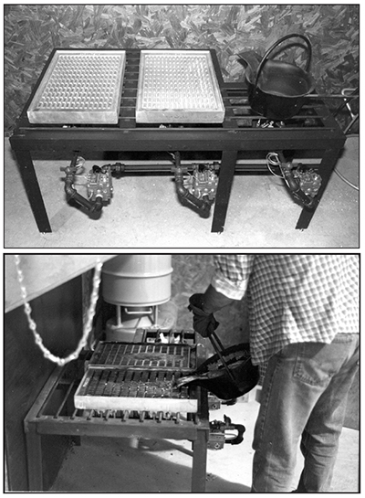
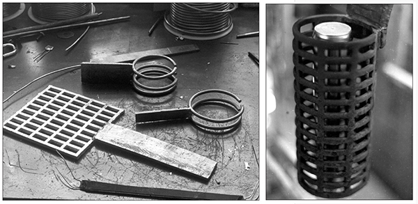
Lead fumes are also given off by the gridmat casting process (Exhibit 3-35). A steel exhaust hood and exhaust system can be installed to prevent the fumes from being released into the shop environment. Both of the exhaust ventilation systems shown have canister-type filters to extract the lead from the exhaust air stream before discharging outdoors.
A welded steel frame holds the aluminum gridmat molds and the lead pot. Three commercial gas burners provide the needed heat for the lead pot and molds. Once the lead is molten, it's poured into the molds, and the gas burners under the molds are turned off. When the lead has solidified in the molds, the gridmats are ejected.
If the gridmats are to be bent, it's best to do it while they are still warm from the mold. The lead gridmats will crack more easily if they are cold and aged. After forming them to the desired shape, the gridmats are welded to each other to form sections. Then the sections are welded together to form the anode body (Exhibit 3-36).
 |
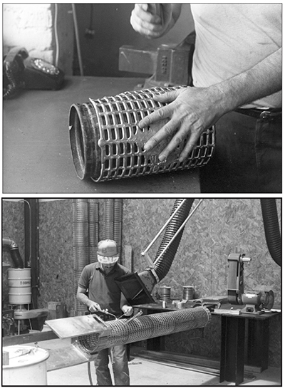 |
| Exhibit 3-35. ANODE CASTING: Molten lead is poured into aluminum molds. | Exhibit 3-36. TOP: Forming the cast gridmats. BOTTOM: Welding the segments together. (Note: These photographs show the workers hands not being protected by gloves. This is not considered good practice.) |
The large attachment leads shown in Exhibit 3-36 were cast in a different kind of mold, then welded to the anode body.
After scraping the lead oxide film from the top portion of the attachment leads to assure good contact, the copper crossbars are attached (see crossbar in Exhibit 3-38). Each crossbar has an insulator under one end, so that the anode will be connected to only the positive tank top bus bar during plating. The crossbars are usually placed at a location that will place the top of the anode slightly above liquid level when submerged in the chrome bath.
 |
 |
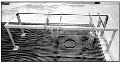 |
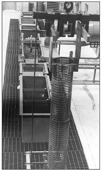
| Exhibit 3-37. Assortment of conforming anodes. | Exhibit 3-38. Using the hoist to lower an anode into its storage area. The cylindrically shaped anode at left has been removed from the plating tank to make room for another size anode. Shops can make custom lifting fixtures to safely handle these heavy anodes. | Exhibit 3-39. ANODE STORAGE in unused area above a secondary containment pit. |
Exhibit 3-37 shows an assortment of conforming anodes that would be appropriate for plating cylindrically-shaped parts, such as shafts or hydraulic rods.
Four of five of the tall anodes in the background of Exhibit 3-37 are OD anodes – that is, they will plate the outside diameter of parts. Anode D, with a single 2 in. square copper crossbar, is an ID anode, used for plating bores. The two short anodes (F and G) in the foreground are to be mounted on reversible racks. The parts being plated by them will load from the bottom.
A hard chrome plating shop will usually have more anodes than will fit in the plating tanks at any given time. Typically, they are built with varying diameters to accommodate different parts that vary in diameter. The overhead hoist system should be built strong enough to carry the heavy anodes from the plating tank to their storage area (Exhibits 3-38 and 3-39).
Anodes are not always simple shapes; complex parts may require the design and fabrication of some very interesting anodes (Exhibit 3-40).
When designing a hard chrome plating line, it's important to include an anode storage area. The storage area should always have a containment system to catch any drips or scale that may fall from the anodes when in storage.
 |
 |
| Exhibit 3-40. Interesting conforming anodes. | Exhibit 3-41. Flat anode. |
Although long conforming anodes like the ones shown in Exhibit 3-38 may be fabricated in a horizontal orientation, once placed in service they should remain vertical. The lead is soft, and laying them down will often bend or break them. The anode storage area should be designed to store them vertically.
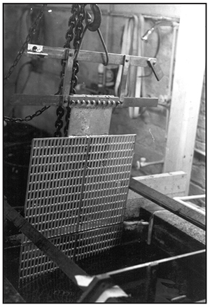
Not all conforming anodes are curved. Exhibit 3-41 shows four gridmats that were welded together to form a flat anode. The anode is hung vertically in the tank, and can be used for plating flat parts. Because the tanktop copper bars were too high for the anode's attachment lead, a copper extension was added beneath the copper crossbar. The copper crossbar has an insulator affixed to the left side.
 |
 |
| Exhibit 3-42. GANGED ANODE: Anode shown can plate up to 8 parts at once. | Exhibit 3-43. ID ANODES: For plating bores. |
Ganged anodes in Exhibit 3-42 are useful for high production runs of identical parts. The anode shown can plate eight parts simultaneously.
Deposit uniformity is improved when the anode is equidistant from the part. The two anodes shown in Exhibit 3-43 have plastic centering disks that ensure that the bottom of the anode will be centered in the bottom of the bores being plated. The disks line up with an unplated area at the bottom of the parts. A job shop that uses reversible racks will usually fabricate many small anodes (Exhibit 3-44). These small anodes are easier to make than the large ones, and take up less space in storage.
 |
 |
| Exhibit 3-44. SMALL ANODES: Assortment for use with reversible racks. | Exhibit 3-45. NO MASK ANODES: Precise deposit control from fast, reusable tooling. |
No Mask Conforming Anodes
When the same type of parts are plated repeatedly, it's a good idea to develop or purchase reusable tooling. In Exhibit 3-45 conforming anodes are encapsulated in plastic housings that serve as the masking components. The chromium deposition is fast, and the distribution of the chromium is highly controlled. Multiple anodes can plate different regions of the part simultaneously, and the lating to the regions can be stopped at different times to achieve the desired deposit thickness.
Solution Heating
Hard chrome plating takes place at a temperature that is hotter than room temperature. Some chrome plating is done as low as 110 degrees Fahrenheit, but is normally in the 125 – 140 degree range. Most of the tank lining systems used for hard chrome plating tanks are not rated for continuous use above 140 degrees. Specialty tanks, having titanium or acid brick lining systems, can withstand higher temperatures.
The heating system must be capable of elevating the plating bath from ambient temperature to its working temperature over a period of time that is practical for the situation at the plating shop. If parts are plated during only one shift, the tank can be unheated for a portion of the other two shifts. However, the heating system must be programmed to preheat the tanks just before the next plating shift. It always takes more kilowatts (kW) or British thermal units (BTUs) per hour to preheat a tank than to sustain it after it has reached its working temperature. The heating system must be sized for a much higher heating capacity if shorter prewarm times are needed. For example, a large tank that needs only 14 kW to maintain 135 degrees Fahrenheit could require 34 kW to warm the tank from 65 degrees to 135 degrees Fahrenheit, or even 64 kW for a 4 hour warmup. Obviously, allowing longer warmup times can really help to minimize the size and cost of the installed heating system.
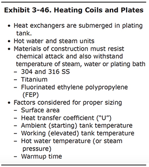
Various factors relating to solution heating are summarized in Exhibit 3-46 and discussed below.
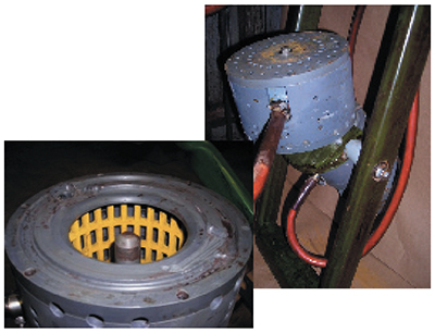
Heating - Materials of Construction
Submerged heaters are placed in harsh chemical environments, and must be built from appropriate materials. Titanium heaters are a good choice for conventional, sulfate only chrome plating baths, but they would be quickly attacked in fluoride chrome baths. Fluoropolymer heaters made of PTFE hold up well in fluoride chrome solutions. 304 and 316 stainless steel heaters can be used in the alkaline cleaning and stripping tanks.
Electric, Over-The-Side Type Heaters
Electric, over-the-side-type heaters are very common in hard chrome plating lines. They are constructed by placing electric heating coils inside of cylindrically-shaped tubes or sheathes. The heaters are generally mounted on a tank rim so that the heating elements are submerged in the bath.
If the solution level gets so low that the heating coils are no longer submerged, tank liner damage is probable, and this dangerous situation can even cause a fire. For this reason, over-the-side-type heaters should always be specified with extended "cold zones" at the top portion of the tube. In this configuration, an extended length of unheated tube is constructed at the top of the tube, which places the heating coils farther down into the liquid. These heaters can also be ordered with lower watt-density. The manufacturer will construct the heater with larger tubes or sheaths to accommodate the fact that the lower watt-density heating coils are spread out over a longer tube with increased surface area. Heaters with extended cold-zones and lower watt-densities cost more, because of their larger physical size, but they are a good investment when safety is a concern.
All process tanks that use electric heaters should also incorporate a liquid level sensor system. This system is wired so that it automatically turns off the heaters if the liquid level in the tank gets too low. Otherwise the heater may cause a fire by igniting the tank liner.
Heating Coils and Plates
Electricity isn't the only heat source that can be used to elevate the temperature of process tanks. Many facilities have an abundant supply of hot water or steam which can be used. In this case, the hot medium is circulated through submerged heat exchangers in the process solution. These heat exchangers are manufactured from titanium, stainless steel, fluoropolymers and other materials that offer good chemical resistance for the application at hand.
Many factors are taken into account when sizing these heating coils and platecoils. These factors include: the effective thermal transfer area, the heat transfer coefficient for the material of construction, the working and ambient tank temperatures, hot water temperature, steam pressure and warmup time. The sizing calculations can be difficult for the plating shop, but are routinely performed by the equipment vendors.
It's interesting to note that, for a given heating load, the fluoropolymer heat exchangers require a larger surface area to compensate for their lower heat transfer coefficient.
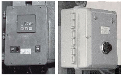
Exhibit 3-47. Digital indicating control. Nonindicating control.
Heating - Controls
In order to maintain the desired temperature, the tank's heaters require some sort of control system. Legacy mechanical controls have largely been replaced by modern, electronic, digital controls which are far more accurate. Typically, the displays have digital readouts for both the setpoint and actual tank temperatures. Most have proportional control circuitry that negates the tendency to "overshoot" the setpoint temperature when the heaters are warming the bath. The control system's temperature-sensing probe should be covered in a sheath material that is chemically-resistant to the process solution. PTFE sheaths work well with chrome plating, alkaline cleaning and alkaline electrostripping baths. Two examples of heating controls are shown in Exhibit 3-47.
Solution Cooling
Although hard chrome plating tanks require preheating, they may also need to be cooled to maintain the proper temperature during lengthy plating cycles. This cooling requirement comes from the fact that the hard chromium electroplating process is so inefficient. Most of the energy applied to the tank from the plating power supply generates heat, while only a small percentage of it deposits the chromium.
In order to determine whether or not a cooling system is needed, or the size of one if it is, you have to compare the heat introduced to the tank with the amount of heat the tank is capable of expelling through natural convection and evaporative losses. If the heat introduced exceeds the natural tank losses, the temperature of the plating bath will rise unless a cooling system is provided.
Most cooling systems pump cool water through submerged coils or plates to extract heat from the plating bath. It's possible to pass ordinary city water through the exchanger, and then to a drain, but this is not recommended. This one-pass approach will use high volumes of water. Also, if the submerged heat exchanger develops a leak, toxic chromic acid will be released to the drain. This is not the way to set up a cooling system.
A better approach is to use recirculated water through the submerged heat exchanger. This recirculated water may be cooled by a chiller or evaporative cooling tower. An alarm system using conductivity, colorimetric or pH sensors should be set up, to notify personnel if a leak develops in the tank coil that adds chromic acid to the recirculated fluid. Also, routine visual inspection and lab analysis of the recirculated fluid is suggested.
The submerged tank coils or plates are the same kind discussed earlier in the heating section, only instead of hot water or steam, cool water is used. They must be made of materials of construction that are appropriate for use in the hot chromic acid bath. The equipment vendor will usually have someone who can properly size the heat exchangers if you are not able to perform the thermodynamic calculations. Smaller, lessexpensive heat exchangers are required when chillers are used, because the temperature of the recirculated water is lower.
Common Cooling System – Cooling Coils and Cooling Tower
In cool, dry climates, evaporative cooling towers can be used to provide a cost-effective cooling system. The towers remove heat from water through a physical process known as "heat of evaporation." The hot water is pumped to the top of the tower, where it falls by gravity through packing media to a bottom sump and drain line. A fan blade blows air across the packing section to increase the evaporation rate. The un-evaporated water reaching the sump and drain is lower in temperature, due to heat losses associated with the evaporation process.
Solution Agitation
Solution agitation can help with both chemical and thermal uniformity and improve rinsing efficiency. Also, it can reduce pitting problems in the chrome plating bath by dislodging hydrogen bubbles from the part surfaces during plating.
Heat rises in heated tanks. With vertical, unagitated tanks, temperature stratification can be significant, resulting in a temperature difference of 5-10 degrees Fahrenheit, or more. It's a good idea to install an effective solution agitation system to any tank where temperature control is important. For example, a hard chrome plating tank should not vary more than a couple of degrees Fahrenheit from top to bottom.
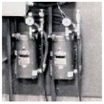
Exhibit 3-48. Two lowpressure, oil-less rotary vane compressors mounted on wall, They deliver oil-free mild air to process tanks.
Tank lip-mounted mechanical agitation can be achieved by pumping the process fluid within the tank. This system works well with both chromic acid and alkaline tanks in the chrome plating line. Air agitation is common for chrome tanks, but can't be used in alkaline tanks, where foaming is an issue. Air agitation is created by using oil-less, low-pressure air from a rotary vane compressor, never from shop air (Exhibit 3-48). If shop air is used, high-pressure air can blow the dangerous chemicals out of their process tanks if a pressure-reducing regulator should fail. Also, any lubricating oil that may be introduced into the process solution is harmful.
Exhaust Ventilation and Air Pollution Control
A modern ventilation system for hard chromium electroplating systems has two important tasks. First of all, it must prevent harmful fumes from infiltrating the air in the plating shop. Secondly, it must remove nearly all of the captured chemicals before the exhaust air is discharged outdoors. Neither task is simple, and taken together, they can be a difficult challenge.
Hazards of Hexavalent Chromium
In the United States, human exposure limits for chemical substances are recommended and reviewed annually by the "Threshold Limit Values for Chemical Substances Committee" of the American Conference of Governmental Industrial Hygienists, often referred to as ACGIH. Each year, they publish a list of current Threshold Limit Values, or TLV's, and Biological Exposure Indices, or BEI's.
The ACGIH TLV for water-soluble hexavalent chromium compounds is 0.05 milligrams of chromium per cubic meter of air. This is a time-weighted, average concentration for 8-hour workdays and 40-hour workweeks. This represents the maximum concentration that nearly all workers may be exposed, day after day, without adverse effect.
Also in the U.S., the Occupational Safety & Health Administration has published an occupational exposure limit for chromic acid. In 2006, OSHA's Permissible Exposure Limit, referred to as a "PEL", was lowered from 52 micrograms per cubic meter of air in the workplace to the very low value of 5 micrograms per cubic meter.
Since the studies and findings of numerous worldwide agencies reflect the growing concern that exposure to even low levels of hexavalent chromium is hazardous to human health, it is critically important that the exhaust ventilation and air pollution control systems are effective. Let's take a look at the ventilation systems in common use.
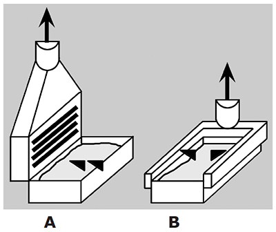
Exhibit 3-49. Conventional tank exhaust hoods: (A) Slotted plenum fishtail; and (B) lateral slot.
Exhaust Hoods
Process fumes from etch, clean, strip and plating tanks in a hard chromium electroplating line must be captured before they escape into the plating room atmosphere. Also, the fumes should not move across the breathing zone for an individual operator as they travel from the process tank to the exhaust hood.
General-purpose room ventilation won't meet these criteria, and should never be used in chrome lines. Instead, each process tank requires its own exhaust hood, mounted on or near one or more rims of the tank (Exhibit 3-49). The exhaust fan for the hood, and the slot openings in the hood plenums, must create an air flow field with a velocity high enough to capture and entrain process fumes emanating from the surface of the bath.
ACGIH publishes tables that specify the recommended minimum exhaust flow rate and air velocity deemed necessary to capture fumes from various industrial processes, including those common to hard chrome plating lines. In practice, it's better to exceed these minimums.
Some tanks are fitted with a single, upright hood on the back rim of the tank. These hoods often have multiple rows of hood slots on the front face. The logic behind this design is that any fume that rises high enough to be missed by the lowest slots might be captured by the higher slot rows. This design works better for non-electrified tanks, like a hot soak clean tank. But electrolytic tanks, like chrome plating tanks with a two buss bar arrangement, often have tanktop copper running over the back rim. In this case its best to have a single slot at the bottom of the hood that can effectively capture all the chromic acid mist below the tanktop copper. Otherwise, the copper will be dissolved by the chromic acid mist flowing over it.
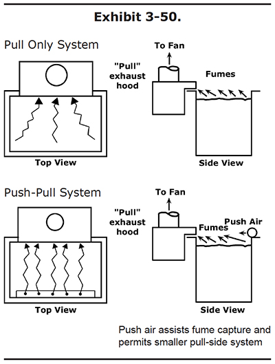
Modern exhaust hoods often have internal composite meshpads that remove process fumes from the exhaust air stream before they can corrode ductwork of other vent system components. In some applications, the hood meshpads serve as the only air pollution control devices in the system. In other situations, the hood meshpads serve as prefilters to reduce the inlet loading on the primary air pollution control devices downstream.
Pull-only and Push-pull Exhaust
Diagrams of pull-only and push-pull exhaust systems are shown in Exhibit 3-50.
Pull-only exhaust systems are commonplace and effective, but they require large air volumes. It's expensive to produce this large air volume, and also to replace it with conditioned air so that the plating shop building doesn't end up with a negative air pressure.
Push-pull type vent systems add an additional air system that delivers a stream of air from the front of the tank to direct the process fumes toward the exhaust air hood. This makes the exhaust hood more effective in capturing all of the fumes.
With either system, cross draft air movement in the plating room will interfere with the ability of the exhaust system to capture process fumes, and therefore should be avoided. Personnel cooling fans should not be placed so that they create such a cross draft. Open overhead doors are another common source.* (*Keep in mind that your air exhaust system is designed to operate optimally when external doors are closed. By opening outside doors, you may cause chromic acid fumes to enter the workplace. Long-term exposure to hexavalent chromium is a dangerous health hazard.) Push-pull vent systems are less susceptible to cross drafts than pull-only systems.
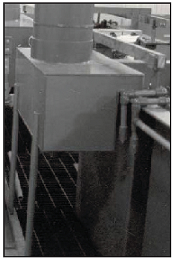
Exhibit 3-51. EXHAUST HOOD: Side view of exhaust (pull) hood mounted on back rim of plating tank.
The pull-only exhaust ventilation system shown in Exhibit 3-51 may have an exhaust hood on one, two or three rims of the plating tank. It's unusual to have all four rims exhausted, since this would make it difficult for the plater to work the tank. Although common, this exhaust hood arrangement is very sensitive to even minimal cross-drafts in the plating room. Also, if the tank loading is high, and a lot of racking members interfere with exhaust air flow, fumes emanating from the front of the tank may escape to the plating room atmosphere.
The push-pull configuration will usually enhance the capture efficiency of the exhaust hood, as the jet stream of air from the pushair pipe, manifold or hood directs the fumes toward the exhaust hood slots.
Encapsulating Hood
One novel hood design encapsulates the top region of the chrome plating tank entirely (Exhibit 3-52). A gasketed membrane allows the hydrogen and oxygen gas generated by the plating process to escape. The chromic acid mist condenses on the interior surfaces and is returned to the process bath. A very small exhaust fan system is used to evacuate chromic acid mist at the end of the batch plating cycle, just before opening the hood to remove the plated parts. This encapsulating hood system can save energy and costs, but the plating process for all parts in the tank must be stopped or interrupted for the evacuation and removal of any plated part.
Even with this drawback, many shops have successfully implemented this technology by grouping parts based on required plating time.
Exhaust Fans
Fans or blowers are used to create the air flow needed to capture the process fumes, transport them to the air pollution control systems, then discharge the clean air out the exhaust stack.
Belt-driven centrifugal fans (Exhibit 3-53) are the norm. They can be easily configured for horizontal or vertical air flow, and are very reliable. Impellers, drive belts and fan motors can be replaced in the field. It's best to protect fans from harmful process chemicals by placing them downstream of the air pollution control device.
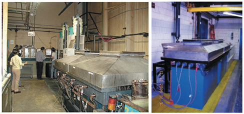 |
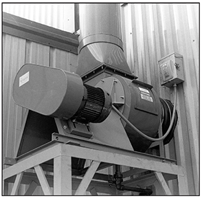 |
| Exhibit 3-52. Novel encapsulating hood design for a chrome
plating tank controls process fumes without the need for a large exhaust air volume.
At end of batch, rectifier is stopped, residual fumes are removed, hood is opened to |
Exhibit 3-53. EXHAUST FAN: Vertical, centrifugal exhaust fan. |
The impeller design, rotational speed and motor horsepower must be properly sized to deliver the required volumetric air flow at the pressures experienced by the system. For a given application, a larger fan size will often be quieter, at a lower rotation speed, than a smaller fan that spins faster. Overall fan efficiency varies with these factors, and it's important to consider efficiency when specifying a fan.
Environmental Releases of Chromium to Air
Great care must be taken to prevent releases of hexavalent chromium from electroplating sources to the environment, including releases to air, to water and to earth. This means that all hexavalent chromium-bearing solids and fluids in the plating shop must be contained, controlled and recycled or disposed of properly. Releases to air are easily prevented by the installation, use and maintenance of an effective exhaust ventilation and air pollution control system. Modern meshpad mist eliminators have removal efficiencies in excess of 99.7% or higher, so the amount that is released to the outdoor air is very small. After this cleaned exhaust air disperses into the earth's atmosphere, fallout concentrations of chromium are extremely low.
Air Pollution Control
Process fumes from a chrome plating line are captured by hoods and entrained in the exhaust air stream, but are not discharged directly outdoors.
Air emissions from the chrome plating tank contain hexavalent chromium compounds, which are considered hazardous even at very low concentrations. For this reason, they are regulated by OSHA inside the plating room, and by the U.S. Environmental Protection Agency (EPA) when discharged from the exhaust stack.
In 1995, EPA promulgated National Emissions Standards for Hazardous Air Pollutants (NESHAP) that cover hard chrome plating operations. The '95 rule required that chromium emissions from hard chrome plating tanks did not exceed a maximum concentration limit of 0.015 milligrams of chromium per dry standard cubic meter of air. Compliance was demonstrated by a one-time stack test. These standards were amended in 2004 to allow an alternative method of compliance, based upon the use of fume mist suppressant chemical additions to the plating bath (Exhibit 3-56). In this case, compliance is demonstrated by adding sufficient chemical fume suppressant that the surface tension of the bath does not exceed 35 dynes/cm when measured by a tensiometer, or 45 dynes/cm when measured by a stalagmometer. In addition, tanks that are fitted with the encapsulating hood design can demonstrate compliance by meeting a milligram per hour limitation based upon surface area of the plating tank.
Exhibits 3-54 and 3-55 show the installation and use of stack testing equipment.
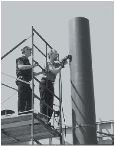 |
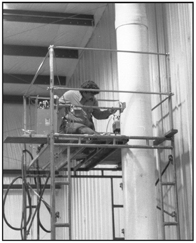 |
| Exhibit 3-54. AIR TESTING: Installing sampling ports in an exhaust stack prior to measuring chromium emissions. The ports can also be used for measuring air volume and speed. | Exhibit 3-55. STACK TEST: Regulatory compliance with USEPA chrome NESHAP. |
Types of Air Pollution Control Devices Used
Vertical moisture extractors
Vertical moisture extractors were among the simplest and least effective. The devices were typically installed in the vertical exhaust stack, after the fan. If you looked at the inside, you'd see a radial array of stator blades placed in the interior of a cylindrically shaped housing. As the exhaust gas stream passed through the device, the air was caused to spin as it passed the stationary blades, and the heaviest chromic acid droplets were deposited on the interior surface of the housing. A drain line returned the collected chromic acid back to the plating tank. Vertical moisture extractors were not very efficient, because only the larger, heavier droplets were removed.
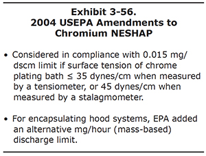 |
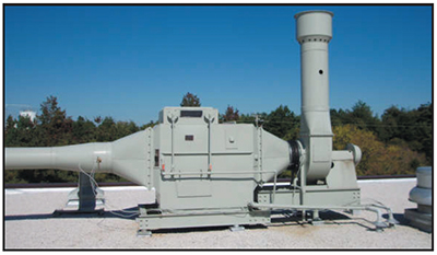 |
| Exhibit 3-57. Roof-mounted scrubber. |
Wet, packed-bed scrubbers
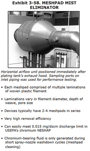 |
Wet, packed-bed scrubbers (Exhibit 3-57) were more popular, and some are still in use today, mostly in legacy chrome plating tanks that preceded the chrome NESHAP. Wet scrubbers usually have three sections. First, a moisture extractor section uses a series of blades to extract the largest droplets. After that, air flows through a packed-bed section filled with plastic media that is continuously flooded with recirculated water from a reservoir. In this section, chromium is removed from the air stream and placed into the recirculated scrubbing "liquor." The third and final stage contains a meshpad mist eliminator or other component to remove the residual fluid from the previous wetted bed. Wet scrubbers have a much higher removal efficiency than the moisture extractors. However, they are not always able to meet the 0.015 milligram per dry standard cubic meter discharge limit of EPA's chromium NESHAP. Also, they generate a lot of chromium-bearing fluid, since the recirculated scrubbing fluid must be replaced with clean water on a regular basis.
Meshpad mist eliminator
Modern hard chrome plating systems rely heavily on meshpad mist eliminator technology (Exhibit 3-58). Plastic filament of varying diameter is woven into a kind of plastic screen. The weave will often take a honeycomb or other three-dimensional shape. Multiple laminations are sewn together or placed in plastic cartridges to form meshpads, and then a series of these meshpads are placed in series in the exhaust air flow. Many exhaust hoods now have internal meshpads, to remove the chromic acid mist before it reaches the ductwork. However, most exhaust systems for hard chrome plating tanks usually incorporate stand-alone air pollution control devices based on meshpad technology. These meshpad mist eliminators can be configured for either horizontal or vertical air flows.