Hard Chrome Plating Training Course
Section 4—Plating Procedures
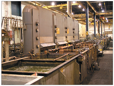
Exhibit 4-1. Hard chrome plating line at an aircraft repair facility. Courtesy of Delta Airlines.
If you give one of the same parts to ten different hard chrome shops without specific instructions, chances are that each shop will use a slightly different set of plating procedures. Further, you will discover that the resulting qualities of the chrome deposits vary, and that some shops take more time to finish the job. There are a couple of key factors in play here:
- Plating equipment/processes. Platers make use of existing equipment and processes, which vary from shop to shop. For example, most military hard chrome shops use wax or plastic maskant, whereas many commercial job shops rely on vinyl tapes. The types of racks, fixtures, anodes, power supplies and cleaning methods employed also vary significantly from shop to shop.
- Plating techniques. Platers often have different approaches to plating the same part, some good and some bad. Although high quality plating can be achieved using different techniques, one thing that you will find at every quality shop is consistency; by applying the same good techniques from part to part, you will have superior results almost every time.
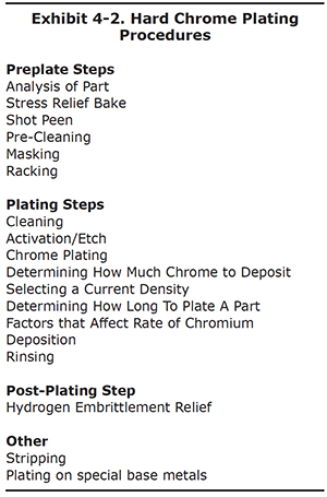
This section of the course covers the range of hard chrome procedures you will need to successfully plate most of the parts you encounter. We will start the discussion with pre-plating procedures, such as cleaning and masking. We then cover plating, and finally conclude with post-plating procedures, such as hydrogen embrittlement relief. The full set of procedures is shown in Exhibit 4-2. At the end of Section 4 are instructions for plating special base metals, such as aluminum and cast iron. Several appendices support the Section 4 discussions, including:
- Reverse etch table for different base metals (Appendix 3),
- Calculation of surface area (Appendix 4),
- Using a plating log (Appendix 5), and
- Amps vs. Volts – Which one is best for controlling the plating process? (Appendix 6).
Please note that this is a comprehensive training course containing commonly used procedures. Your procedures may vary considerably. Please review your technical orders for local specific plating procedures.
Preplate Analysis
Parts arriving at the plating shop should always be examined for serious defects at an early stage. It's important to spot any pits or other imperfections before plating the part; otherwise, you could waste a lot of time and money.
To perform this step:
- be certain the part is sufficiently clean, so that dirt or surface films don't hide the defects
- use bright lighting to assure an accurate visual inspection
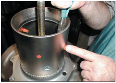
- use a flashlight and inspection mirror to check inside diameters (Exhibit 4-3)
- use a magnifying glass or low-power inspection microscope when looking for small imperfections.
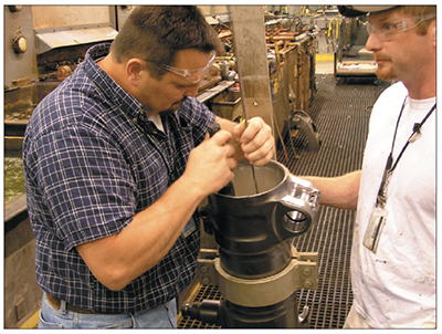
Exhibit 4-3. Using a flashlilght and inspection mirror, a plater conducts a careful pre-plate examination inside of a landing gear piston. Courtesy of Delta Airlines.
In addition to these basic inspection procedures, note that critical parts, like those used for weapon systems or aerospace may require dye-penetrant inspection, magnetic particle inspection, or other sophisticated inspection methods.
During the pre-plate inspection, look for surface blemishes that could make the part unsuitable for plating. Most notably, search for cracks, pits, nicks, dents, cuts, or gouges. It is unlikely that a chromium deposit will fill in or bridge these flaws. Chromium deposits tend to follow the shape of the base surface, and will actually plate faster on sharp or raised edges (unlike copper or nickel, which tend to fill in low spots and "level" the surface). Remember, chrome plating always exaggerates any marks in the base metal.
Depending on the severity of the surface defects, the part may need filing, lathe turning, grinding or belt-polishing to remove them. Typically, base metal is removed until the imperfections clean up. This is an expensive solution, because it creates the need for a thicker layer of chromium to make up for the base metal removed. This technique is usually used when there are many defects on the region to be plated.
If only a few problems exist, and if specifications allow, it will be faster and more cost-effective to fill in voids. For example, pits can be filled using a "dot welder" that electrically heats a small metal sphere and the base metal until both become molten and are fused. Other welding systems may be better suited for larger defects, or those that may have elongated shapes. The welding techniques can save time, money and energy if they result in reduced grinding and chromium thickness.
Sometimes, you will encounter a situation where chrome plating may not be feasible:
- Specifications may limit the smallest size that the part may be ground, and if defects go beyond that limit, they can't be removed.
- Some parts have specifications that limit what repairs can be made: for example they may prevent you from filling in voids.
In such cases, it is best to discuss these issues before plating the part. Show the part to the customer (or management) and explain why it probably will not plate acceptably. This could avert some subsequent bad relations.
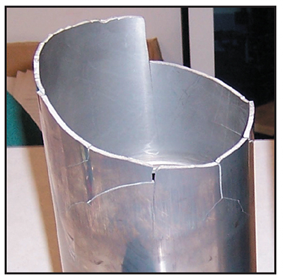
Exhibit 4-4. High strength steel part that fractured in the plating tank. The suspected cause was insufficient stress relief before plating.
Stress Relief Bake
Metalworking operations performed on parts prior to hard chrome plating can have adverse effects by
inducing stresses in the part. For example, wheel grinding, stone honing and various polishing operations can add
tensile stress1 in an orientation that tends to cause cracking or fracture of the part. As a result, the
fatigue limit, or fatigue strength, of the part is reduced. High strength steels are more susceptible than most
other metals to tensile stress.
(1 Knowing the difference between tensile and compressive
stresses is important for platers. Tensile stress causes materials to elongate
and possibly be pulled apart. For example, a rope used in a tug-of-war is under tensile stress.
Compressive stress occurs when forces push into an object. For example, a pillar supporting a
building is subject to compressive stress. When a long, thin object is supported horizontally
at its ends and pushed down at the middle, the top edge is under compressive stress and the
bottom edge is under tensile stress.)
Pre-existing tensile stress is particularly harmful to parts that are hard chrome plated because the chrome plating process will induce additional tensile stress in the part. These stresses can accumulate within the part to such an extent that they fracture a part in the plating tank (Exhibit 4-4). Therefore, many parts must be treated to remove tensile stress before plating.
Preplate baking is the most common method to remove preexisting tensile stress. It is performed in an oven under controlled conditions. Various industrial and military specifications prescribe the baking parameters. Commonly, hard steel parts are baked at 375°F for a minimum of 3 hours. This bake is performed after all machining operations and before shot peen, if performed.
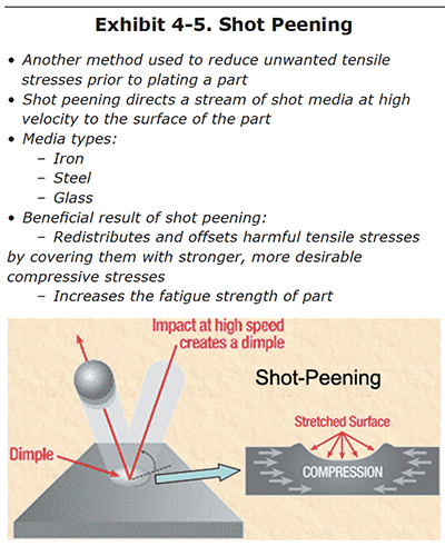
Shot Peen
Shot peen is another common approach to reduce unwanted tensile stresses in the part prior to plating (Exhibit 4-5). During shot peen, the part is placed in an enclosing cabinet and is bombarded with spherically shaped media made of iron, steel or glass (Exhibit 4-6). The repeated impact of the media deforms the outer surface of the part, inducing a more desirable compressive stress that is oriented parallel to the surface. Existing tensile stress may still be present, but is reduced and are now beneath the much stronger compressive surface stress. The overall effect of the shot peen is to increase the fatigue strength of the part.
Pre-Cleaning
Not all parts require a cleaning step prior to masking or racking. However, if the part is not clean enough for tape, wax or lacquer masking to adhere properly, some sort of pre-cleaning will be needed. If the masking does not completely adhere, it will likely lift at the edges and result in chromium deposition or etching where it isn't wanted. Precleaners and activators (acid etches) are often harmful to exposed substrates. This is particularly true when they get trapped and the rate of etch increases with the warmth of the heated chrome plate solution.
Even if the part does not require these types of masking materials, it may still need one or more pre-cleaning stages before it is racked for plating. For example, used bearings can require multiple cleaning stages to remove stubborn bearing grease.
Various cleaning methods can be used. Often, small or medium parts can be hand cleaned using wet volcanic pumice or non-chlorinated scouring powder and an abrasive pad (e.g., Scotch-Brite®). Many companies make industrial-duty cleaning machines that may involve the use of steam, very hot water, strong acids or caustic chemicals along with high pressures or centrifugal forces, to remove tough soils. Ultrasonic cleaning systems are sometimes used, as well as standard hot soak clean or electro-clean tanks.
An important test for cleanliness is the "water brake test," which is discussed later in this section.
 |
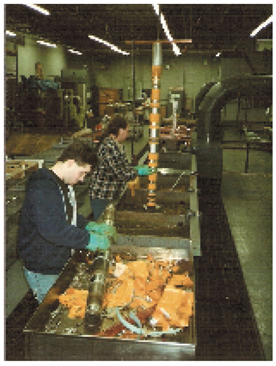 |
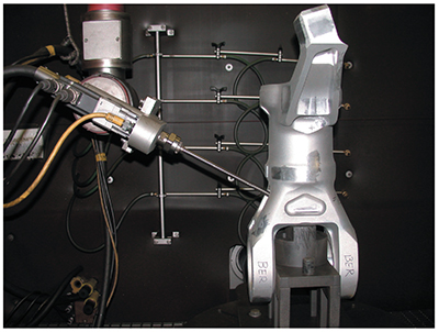
| Exhibit 4-6. Robotic shot peen system processing a helicopter part. | Exhibit 4-7. Worker removing vinyl tape after plating. |
Abrasive-media blasting is often used on hard-to-remove films, corrosion, or scale. Common media types include aluminum oxide, silicon carbide and glass. Another benefit of abrasive blast is that it roughens the surface which helps to promote adhesion by increasing the surface area and providing a basis for mechanical interlock with the substrate.
Glass bead blasting is particularly useful if the preplate grinding operation was not optimum (e.g., if the grinder didn't dress the wheel immediately before grinding, or didn't take light passes that gradually removed steel stock). Grinding mistakes can result in a surface finish that is too rough for plating. The glass bead process will help eliminate this problem.
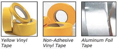
Exhibit 4-8. Common masking tapes (Courtesy of ASI Masking).
Masking
It is unusual for a part to be entirely covered with a chromium layer; more typically chromium is only applied to specific surfaces of the part that require wear resistance. Therefore, the unplated areas are masked so that chromium does not plate in these regions.
In some cases, there is another reason for masking. Certain base metals are chemically attacked by pretreatment or plating chemicals and the unplated areas of these parts are masked water-tight so that they do not come into contact with the solutions in which they are immersed. For example, copper or brass base metals require watertight masking to prevent attack by chromic acid.
Simply preventing chromium deposition is easier than keeping a surface dry. Non-etch baths, like the standard chromic acid/sulfate bath only require masking that blocks the electrical communication between the anode and part. However, if any pretreatment steps are capable of etching the part, watertight masking will be needed.
Repair depots and job shops that perform hard chrome plating often get a wide variety of parts, but small quantities of any single part, from their customers. In this scenario, where the shop may never see the same part twice, the part will probably be masked with tapes and lacquer, or perhaps wax, if it's available. Depending on the complexity of the part, it can take a lot of time to apply the masking before plating, then remove it afterward (Exhibit 4-7).
 |
 |
| Exhibit 4-9. Parts masked using vinyl and lead tapes. Courtesy of Plating Perceptions Inc., Cleveland, OH. |
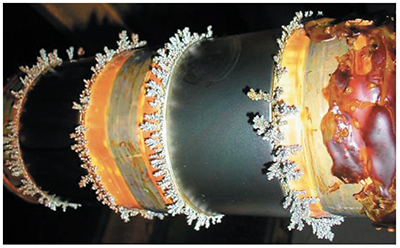
Exhibit 4-10. A steel pin with two journals after plating. Notice that chrome trees have plated onto the edges of the exposed lead tape, but are not present on the journals. |
Conventional Masking
Conventional maskants, often referred to as "stop offs", include:
- tapes,
- plugs, caps and misc. maskants,
- lacquers, and
- wax or plastic.
 |
 |
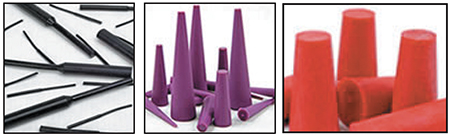
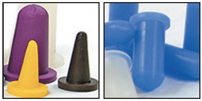
| Exhibit 4-11. Neoprene plugs, multi-purpose plugs, red rubber tapered plugs. (Courtesy of ASI Masking) | Exhibit 4-12. Plater installing a pull-through plug. |
Tapes. There are two basic types of tapes, conductive and non-conductive. These are often used in combination with one another (see Exhibit 4-8). Conductive tapes are made of aluminum or lead, and usually come with an adhesive backing. Lead tape does a better job than aluminum tape for most applications. Aluminum tape is less expensive and is often used to mask off larger areas. Conductive tape is most often used at the edges of a plated surface, where it acts as a current robber.
Non-conductive tape is usually made of thin vinyl plastic. It is usually bright yellow in color and it comes in various widths ranging from ½ inch to several inches. Both non-adhesive and adhesive types are commonly used. Non-adhesive tapes are used to mask off large areas and are then often held in place by several wraps of adhesive vinyl tape. Adhesive tapes may also be used on their own, especially when smaller areas are being masked.
Combinations of conductive and non-conductive tapes are often used. For example, the non-plated edge of a piston is usually first masked with a narrow band of lead tape. Then a layer of adhesive vinyl tape is applied over the lead tape, leaving about ¼ inch of lead tape exposed (see Exhibit 4-9). The exposed lead tape acts as a current robber and provides a gradual "run-out" at the plated edge. Also, chromium "trees" will build up on the tape rather than the part (see Exhibit 4-10).
Plugs, Caps and Misc. Maskants. Plugs are used to mask holes where chrome plating is not wanted. Plugs used in chrome plating are most often made of silicone or neoprene. They are manufactured in a wide variety of sizes and shapes (Figure 4-10). Plugs are made for both blind- and through-holes. Blind-hole plugs are tapered, and look like bottle stoppers. Through-hole plugs have a "handle" that allows the plater to pull the plug through the hole from the back side of the part (Exhibit 4-12). In either case, after the plug is inserted into the part, it is trimmed using a razor knife so that it does not protrude beyond the rim of the hole. Most shops maintain an inventory of different plugs to avoid having to order them each time a need arises.
 |
 |
| Exhibit 4-13. Cone caps & washer caps. (Courtesy of ASI Masking) | Exhibit 4-14. Maskant fabrication materials. |
Caps are used in a way similar to plugs, but instead of masking holes, they mask off protrusions such as nuts and bolt heads (Exhibit 4-13). As with plugs, they come in a variety of sizes. It is important to select a cap that will not loosen and come off during the plating cycle.
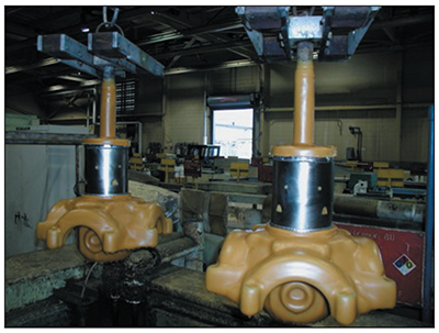
Exhibit 4-15. Aircraft parts that have been masked using wax.
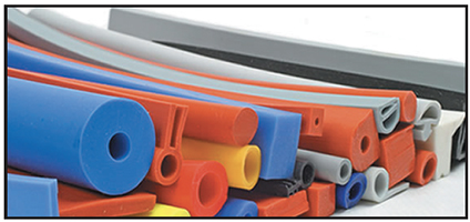
Platers' ingenuity often leads to use of other maskants for solving specific problems, including plastic tubing or cord, plastic sheeting, and washers (Exhibit 4-14). Using these materials the plater can fabricate maskants in the shop. Also, there are a number of suppliers that will custom make maskants to your specifications. When searching for the right maskant, keep in mind two important factors:
- The maskant must stay in place through the entire plating cycle.
- The maskant must be chemically resistant to the pretreatment and plating chemicals. Materials that are chemically resistant to chromic acid include silicone, neoprene, teflon, nitrile, santroprene, hypalon, viton, nylon, polypropylene, and PVC®. Keep in mind that some of these materials may break down or dry out after multiple uses and will need to be replaced.
Wax. Wax is applied by dipping the part into a specially designed heated tank containing a molten wax. Most commercial waxes in use are light tan to dark brown in color. Similar polymer-based materials are also commercially available. Before dipping the part in the hot liquid material, tapes are often applied at the edges of the plated surface. After the part is dipped and coated, and the maskant material has hardened, the tapes are removed to expose a clean edge. The hardened maskant is also removed from the entire surface being plated. The edges of the maskant are then carefully trimmed by hand to create a straight plating line (Exhibit 4-15).
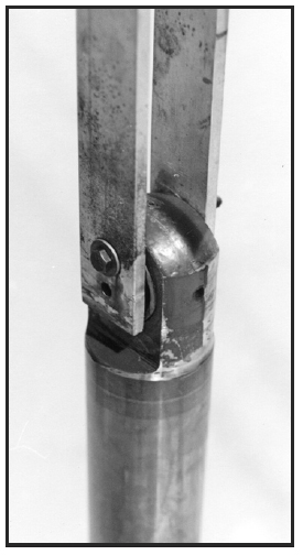
Cathode Robbers and Shields. The application of robbers and shields is usually performed during the masking and fixturing steps. These are used to improve the chromium deposition process.
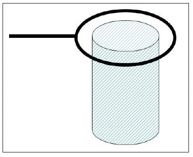
To prevent excessive deposits or "treeing" on high points, which are subject to high current density, auxiliary cathodes (also called robbers or burners) can be used. Generally, these are made from wire and are connected to the cathode. Exhibit 4-16 is an example of this method of protection in the case of a cylinder. During deposition, the wire is heavily plated with chromium and prevents an excessive deposition on the edge of the cylinder.
In a similar way, non-conductive shields can be fitted to screen areas subject to high current density and thus produce more uniform deposits. Exhibit 4-17 shows two non-conductive shields A and B by means of which it is possible to obtain even deposits on the areas a, b, c, d and e, which otherwise would receive an excessive deposit at b and d and a minimum at c. Suitable materials for shields are polypropylene and PVC and similar materials that are chemically resistant to chromic acid.
 |
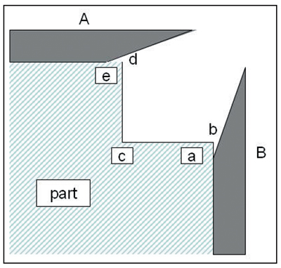 |
| Exhibit 4-16. An example of a cathode robber. The wire is connected to a rack member (negative charge, like the part) and prevents excessive deposition on the top of the cylinder. Adapted from diagram by Paul Morisset, Chromium Plating, 1954. | Exhibit 4-17. Use of non-conductive shields A and B to assist in uniform deposition over areas a, b, c, d and e. Adapted from diagram by Paul Morisset, Chromium Plating, 1954. |
Lacquers. There are a number of chromic acid-resistant lacquers available that can be applied by spraying, dipping or brush application. Most of these are red in color and are solvent-based. Lacquer is most often used on surfaces that are difficult to tape, such as non-symmetrical surfaces or inside diameters.
Maskant Wastes. In most circumstances, the tape, lacquer, and wax masking materials removed after plating will need to be disposed of as hazardous waste. Wax or polymer maskant, which is commonly used by military and aerospace facilities, can create a large volume of waste when it is removed (Exhibit 4-18). Also, many facilities find it necessary to employ vapor degreasers to remove residual wax from the parts. Degreasers can contribute significantly to the quantity of hazardous waste generated.
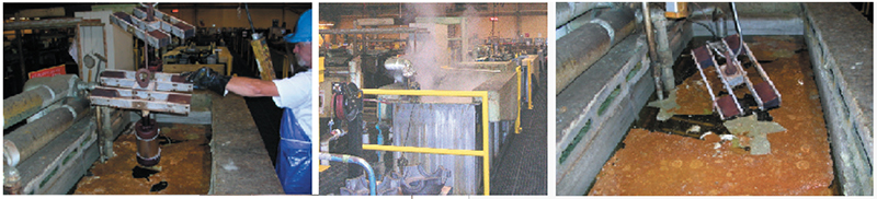
Exhibit 4-18. Dewaxing pictures from WR-ALC.
No-Mask Anodes. A facility plating a medium to high volume of similar or same parts would benefit by investing in rigid, reusable maskants. These can be designed to attach quickly to the part or rack, and are rinsed and reused over and over again. Usually, these masking components are made from plastics, such as PVC, that are resistant to chemical attack by the pretreatment and plating baths.
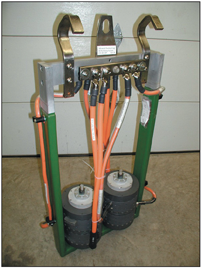
Exhibit 4-19. No mask conforming anode system for plating CH-47 horizontal pins. Courtesy of Advanced Toolling Corp.
The most recent development in this area is hybrid tooling that incorporates reusable masking and conforming anodes. This type of tooling, which is durable and reusable, is termed a "no-mask anode." These fixtures are typically custom designed for a single part, or a group of parts of similar shape (see Exhibit 4-19). Plating shops invest in this kind of tooling when they routinely plate the same parts on a regular basis. No-mask anodes provide numerous benefits:
- Setup and breakdown times for no-mask anodes are very fast, often saving hours of labor for complex parts.
- Close spacing for the conforming anodes results in much higher rates of deposition and shorter plating times than traditional stick anodes.
- The tooling offers a high degree of control over the distribution of the chromium coating, reducing the need for
excessive overplating (i.e., grind stock), and can regulate the amount of run-out at the ends of the
deposit.*
(*Chrome tends to plate thicker at the ends of a shaft than in the middle. The terms "dogbone" and "hourglass" are often used to describe the resultant shape after plating. Normally, the heavier the buildup of chromium, the more exaggerated the deviation in thickness will become; however "no-mask" anodes minimize this problem.) - Encasing the conforming lead anodes in PVC eliminates lead contact with workers and makes the anodes less susceptible to mechanical damage.
Racking/Fixturing
Plating racks and fixtures are used to hold the parts and sometimes also the anodes during hard chrome plating. These
devices can be elaborate customized apparatus or simple holding fixtures.
An example of a simple holding fixture is shown in Exhibits 4-20 and 4-21. During plating, these fixtures would be
placed on the cathode tank bus bar and stick anodes would be arranged around the part for plating. Typically, these
fixtures are made from aluminum, which is a good conductor of electricity.
 |
 |
| Exhibit 4-20. RACK THAT HOLDS ONLY THE PART: (no anodes). A pair of vertical aluminum bars attach to eye end of hydraulic rod. | Exhibit 4-21. WELL DESIGNED RACK: Aluminum fixture holds part vertically, holds up well in chromic acid, and is large enough to supply desired amps. |
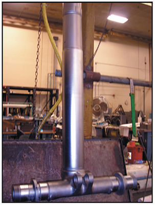
A more elaborate rack is shown in Exhibit 4-21. This device is constructed of aluminum bars (plastosol coated) and has copper hooks at the top, which rest on the tank bus bars. It is designed to be used with conforming anodes and it holds both the part and anode during plating. This rack, which has one anode and one cathode hook, is termed a reversible rack, and it is used with a two bus bar arrangement (see Section 3: 2 Bus Bar Design). It is placed onto the tank bus bars in the "reverse" position for etching, then lifted up and turned 180 degrees and placed back onto the bus bars in the forward, or plating position.
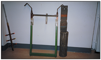
Exhibit 4-22. Reversible rack designed for use with conforming anodes.
Attributes of a Well-Designed Rack
If a plating shop has a high number of smaller-sized parts, the throughput is influenced by the number that can be plated simultaneously. In this scenario, racks that hold multiple parts have an advantage. There is a real benefit to plating five parts at once, instead of a single part.
Usually, some experimentation is needed to optimize the rack. If parts are mounted too close to each other, the distribution of chromium may become a problem. The plated regions facing adjacent parts may plate much slower than regions facing the anodes. In this case, it may be necessary to change the design of the rack to reposition the parts, or to plate fewer parts at once.
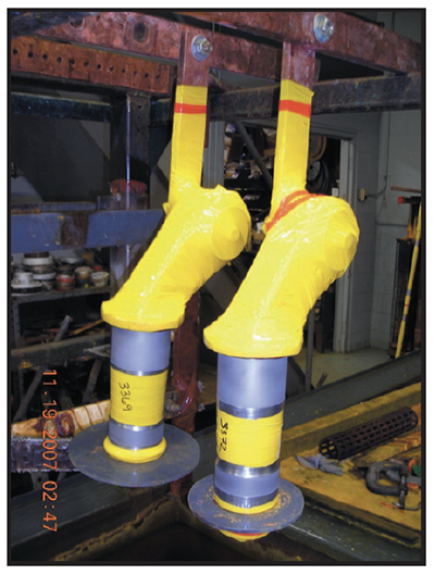
Almost every part to be plated has a preferred orientation. For example, flat parts should be plated vertically. Consider a square plate oriented horizontally. Hydrogen gas that is given off during plating will get trapped beneath the bottom surface, and will probably also adhere to the top surface. The trapped pockets or bubbles of gas will shield these areas of the part from the contact with the plating bath, causing missed spots or thin chromium deposits. If the flat plate is oriented vertically instead, the bubbles will more easily dislodge from the workpiece and rise to the surface of the plating bath.* (*Holding a flat part vertically will eliminate problems with gasing, however, flat parts will tend to plate much thicker at the ends than in the center.) Sometimes a part will require plating on surfaces that are at right angles to each other. In this case, the part may have gassing problems whether it is oriented in either a vertical or horizontal direction. The rack designer or plater may then decide to orient the part at an oblique angle, like 45 degrees, so that perpendicular plated surfaces are neither vertical or horizontal, yet will still allow the hydrogen gas bubbles to break free of the angled surface. However, in some cases when surfaces are at 90 degrees to one another, it is necessary to use two plating cycles. As an example, landing gear pistons have a main barrel and two axles (two or more journals each) that are at right angles (Exhibit 4-23). Usually, the barrel is plated in one operation in the verticle position shown and then the axles are plated in a second operation after the part is rotated 90 degrees.
|
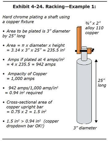
Problem Solving: Exhibit 4-24 shows a part to be plated. Its surface area is approximately 236 square inches. If we plate this part at a current density of 4 amps per square inch, a target current of 942 amps is needed. If a single copper bar is used to deliver the 942 amps, it will have to have at least 0.94 square inches. This is calculated very simply by dividing the required amps by the current-carrying capacity of the copper. See Appendix 4 for calculating surface area. Now let's say that a copper plating fixture already exists at your shop that nicely fits the top of the part. The copper bar is ¾" x 2", resulting in a cross-sectional area of 1-1/2 square inches. Is this large enough to carry the 944 amps without overheating? The answer is YES, because the 1-1/2 square inch area for the bar is
greater than the 0.94 square inches needed to carry the current. Also, be certain that the contact area, where the fixture attaches to the part being plated, meets the minimum square inches (0.94 in2) |
A well designed rack should be easy to load and unload. It should also allow process chemicals to drain freely and quickly, in order to minimize drag-out into rinse water and subsequent process tanks. If the rack has any horizontal members, it's a good idea to drill holes to allow trapped liquid to drain from the rack.
A hard chrome plating rack must deliver the electrical current to the part. This means that it must have the current-carrying capacity needed for the plating amperage. If it is undersized, the rack will overheat during plating and the chromium deposition rate will be less than expected. Particular attention should be paid to this factor with respect to contacts between parts and fixtures.
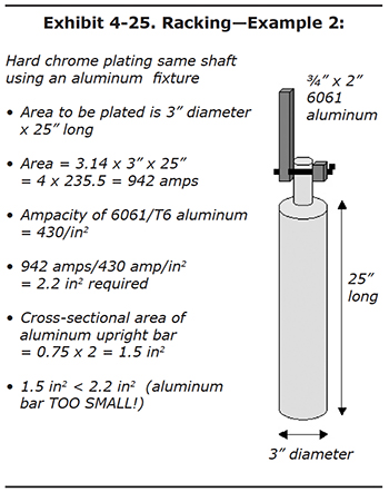 |
Problem Solving: Exhibit 4-25 is the same part, to be plated at the same amps as the previous example. But this time, the plater finds an existing aluminum fixture that happens to be the same ¾" x 2" size. Is a single aluminum bar of this size large enough? The answer is NO. The part needs 942 amps to plate properly, but an aluminum bar with an ampacity rating of 430 amps per square inch would need a cross-sectional area of 2.2 square inches. Our bar only has 1.5 square inches. If no larger aluminum bars are available, but extra ¾" x 2" bars exist, the plater in this example could add an extra upright bar, which would double the current-carrying ability. To deliver 942 amps we need 2.2 square inches. Now we have 3.0 square inches combined for the two aluminum upright bars. Again, it's okay to have more square inches then necessary. In fact this helps the rack to run cool during long plating cycles. |
A critical design aspect of the rack is the hooks that are used to suspend the rack on the tank busing. The hooks, which are often copper, must be designed for good contact by taking into account the shape and size of the tank bussing. Most bus bars are either round or square and come in sizes ranging from 2 to 4 inches (either diameter for round or side measurement for square). In some cases, round bars are machined to flatten the upper edge. In any case, the contact area between the hook and the bus bar must be sufficient to carry the intended amperage.
When necessary, c-clamps should be used to secure the rack hooks to the tank bus bars. The bars and hooks should be cleaned before every use.
The rack must also make good physical and electrical contact with the part, preferably to an unplated region on the part. This generally requires high contact pressures between the rack member and the part.
The rack members must also withstand the chemical attack of the chromic acid plating solution and any other pretreatment process solutions. This is often a conflict. For example, copper bars may hold up well in cleaning tanks, but would be quickly dissolved in chromic acid. Aluminum withstands chromic acid pretty well, but is quickly attacked by the sodium hydroxide present in most soak and electroclean solutions. Many platers use aluminum racks and simply hand-scrub the parts using wet volcanic pumice on an abrasive pad to a water break free condition to avoid this problem.
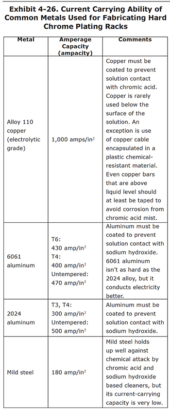
Exhibit 4-26 presents a list of the current-carrying ability of some of the common metals used for hard chrome plating racks. The numbers represent the maximum amperes per square inch of cross-sectional area for a bar ("ampacity").
Jumper Cables
Many hard chrome plating shops rely heavily on the use of jumper cables for connecting anodes and parts to tank busing. Shops typically keep various sizes of jumper cables on hand for different needs. Jumper cables are convenient to use and in many circumstances are adequate for the job. However, jumper cables also tend to be misused. Often, they are undersized and therefore not capable of carrying sufficient current. This becomes apparent when the cable overheats during plating; occasionally to the point where it becomes a fire safety hazard and affects plating quality.
Keep in mind that cables operate under the same rules as bus bars; there must be sufficient square inches of conductor to carry the intended amperage. Exhibit 4-27 shows the current capacity for common cable sizes.
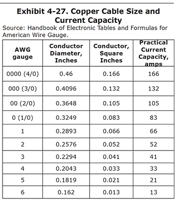 |
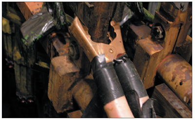 Exhibit 4-28. Auto battery jumper cable in use. Note the small amount of contact area provided by the clamp. |
Always select a larger cable (or multiple cables) than is theoretically needed because any resistance that is present (e.g., dirty bus bars) will diminish its current carrying capacity.
An additional consideration with jumper cables is the cable clamp. Clamps also must provide sufficient square inches of conductor or they become the electrical current bottleneck. Common car battery cable clamps are generally insufficient for plating because they don't have enough contact area and they don't grip very well (Exhibit 4-28). Always use a heavy industrial grade clamp and be certain that it is corrosion free so that it makes good contact.
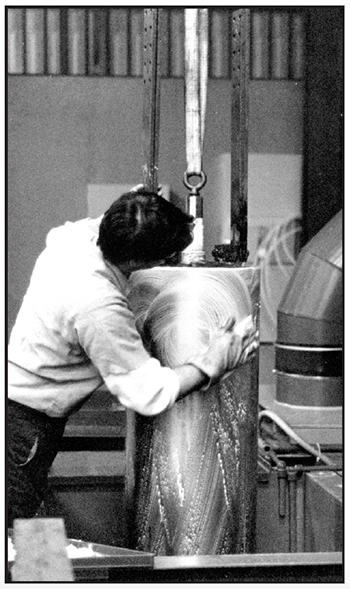
Exhibit 4-29. PUMICE SCRUBBING: Hand scrubbing with
wet pumice on an abrasive pad is an effective cleaning method.
Cleaning
The surface to be plated must be clean in order for the chromium deposit to bond properly. Dirt, grease, oil, paint, marking dyes or any foreign film on the workpiece will weaken the adhesion, resulting in peeled or blistered chrome. In severe cases, it will prevent the chromium from depositing altogether. If the bond was marginal, even if it stands up to the grinding or polishing operations after plating, the useful life expectancy for the part will probably be shortened if the chrome peels, or if it allows corrosion to form between the base metal and chrome layer.
Cleaning is usually performed after racking, where the part and rack go through the cleaning steps together. However, in some cases, it is easier or even necessary to clean the part before racking. For example, if you are using exposed aluminum racks, and you plan to clean the part in an aggressive sodium hydroxide-based cleaner, the solution would attack the exposed aluminum metal.
There are many ways to clean a part before chrome plating. The most common methods are discussed in the following paragraphs.
Abrasive Blasting
Abrasive blasting is generally used for most of the workload (Exhibit 4-30). It provides a good surface for chromium plating. Parts heavily covered with oil and grease will require precleaning prior to abrasive blasting so that the blast media is not contaminated. This should be accomplished with steam cleaning, degreasing, or a soak cleaner.
Abrasive-media blasting is especially helpful with hard-to-remove films, corrosion, or scale. There are many types of blast media available, from oxides or carbide species to ground-up corn cobs and plastic blast media. Aluminum oxide is the most commonly used in chrome plating shops. Glass bead blasting is also common and it is particularly useful for cleaning threaded or other precision areas of parts where more aggressive media would change the shape or contour. Vapor blast (or wet blast) units, which combine blast media and water vapor, are also popular.
It's important to replace blast media frequently so that it is always clean. Otherwise, the blasting procedure may actually impinge soils onto the workpiece.
Alkaline Cleaning
These tanks come in two basic configurations:
- Hot soak clean tanks rely on heated chemicals to remove the grease, oils or foreign films.
- Electroclean tanks add direct current electricity to the cleaning system, making it even more effective.
With either system the cleaning solutions have a complex chemical makeup with multiple components or constituents, and are almost always purchased from vendors as commercial formulations. Very few plating shops formulate their own cleaners from raw chemicals. The cleaning mechanisms for alkaline cleaners are as complex as their chemical makeup:
- Displacement cleaners use surfactants or wetting agents to remove oils, which then float to the surface of the cleaning solution.
- Emulsifying cleaners also use surfactants to penetrate the soils, but they are broken down into small particles that remain suspended in the solution.
- Deflocculation cleaners surround soils and remove them from the surface of the workpiece; the soils end up in suspension.
- Saponification cleaners break down certain types of soils or oils and convert them to water-soluble compounds, which are actually dissolved in the cleaning solution.
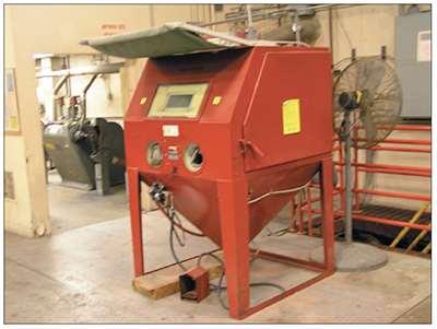
Exhibit 4-30. Abrasive blasting cabinet containing glass bead media.
Different aqueous alkaline cleaners each have advantages and disadvantages. The decision as to which chemistry is most effective for a given application is often best made by the companies that offer the commercial cleaners. The plating shop should specify what soils are likely to be present on the parts to be plated and what types of equipment are available.
With electrocleaning, the part to be cleaned is usually connected to the positive pole of the rectifier, and the bare steel tank walls are made negative. This is referred to as anodic electrocleaning. This arrangement is effective at dislodging soils from the workpiece. Another advantage is that it does not promote hydrogen embrittlement of the part, since oxygen gas is released at the part instead of hydrogen. However, parts which are not susceptible to hydrogen embrittlement may benefit from cathodic electrocleaning, which reduces the amount of carbon or other alloy compositions pulled to the surface. Periodic reversing electrocleaning is very common, whereby the polarity of the rectifier is reversed multiple times during the cleaning process. Usually, the periodic reverse process ends on an anodic cycle.
Alkaline cleaning solutions work better when mechanical agitation is introduced into the tank. One way to accomplish this is the use of ultrasonic waves. The generated waves are radiated into the cleaning solution by transducers. The solution forms gas bubbles that are rapidly and repeatedly compressed and collapsed, which has the effect of dislodging soils from the workpiece.
Small parts are better suited to ultrasonic cleaning than larger ones, due to the high capital costs and power requirements associated with large ultrasonic generators and transducers.
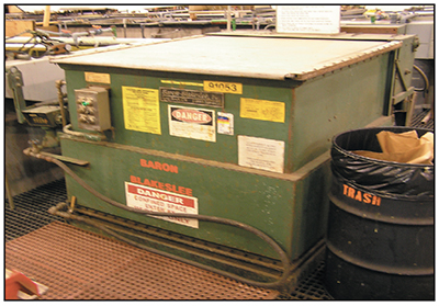
Exhibit 4-31. Common vapor degreaser with roll-top cover.
Solvent Cleaning
At one time chlorinated solvents were used extensively in the metal finishing industry for degreasing and cleaning. The most popular type of equipment was the vapor degreaser (Exhibit 4-31). However, chlorinated solvent use has declined considerably, mostly due to environmental air pollution regulations. Many of the older popular solvents used for degreasing such as trichloroethylene (or TCE), perchloroethylene (or PERC), and methylene chloride (MC) generate hazardous wastes, which are expensive to handle and dispose of under hazardous waste regulations.
Of the solvent cleaning that remains in use today, most is carried out by the aerospace industry, military depots, facilities whose applications require precision cleaning operations, and (to a lesser extent) some facilities involved in general finishing. Even these applications have undergone some changes. Most of these facilities use new solvents such as n-propyl bromide that have been designed for environmental compliance. The equipment used for cleaning and degreasing has also changed significantly. It is often downsized, and is generally much more efficient and less polluting (for example, being operated as totally enclosed systems, or being equipped with carbon adsorption capture devices).
Solvent hand wiping is also used extensively. However, the solvents used for this purpose must be non-toxic. Most often, solvents used for hand wiping are proprietary chemicals that are manufactured specifically for this purpose.
Hand wiping is often performed for cleaning up small areas on parts after masking with adhesive tapes. The tapes can leave adhesive material on the surface being plated, which can interfere with chromium deposition. Hand wiping is also used for removing finger prints that could cause a slight blemish on the chrome deposit.
Hand Scrubbing
Another widely-used cleaning technique is hand scrubbing. For parts that lend themselves to this procedure, it is highly effective. The plater sprinkles some pumice on an abrasive pad and uses hand pressure to scrub the part (Exhibit 4-29). When finished, it is rinsed with water while it is wiped with a clean pad and checked for a water break free surface.
For bright objects that are lightly soiled, a tampico brush may be used instead of the abrasive pad. When larger parts transported by an overhead hoist are cleaned by this method, it is best to install a dedicated scrub tank in the process line. This system has the advantage of using less energy than heated aqueous cleaning tanks, and the use of non-hazardous cleaning substances simplifies disposal.
Cleaning Summary
In summary, the five most common cleaning methods for hard chrome plating are:
- Abrasive blasting
- Soak cleaner
- Solvent degreasing
- Solvent hand wiping
- Pumice scrub
The selection of cleaning methods depends on the available equipment and cleaning needs. Cleaning methods are often used in conjunction with one another. For example, hand wiping with solvent may be used after masking to remove any residual adhesive and pumice scrub may be used just prior to plating to remove any residual soils and fingerprints.
Water Break Test
The water break test (ASTM-F-22) is one of the most important procedures in any plating operation. The test is easy
to perform and
is a reasonably good indicator of surface cleanliness. Make sure you carry out this test after doing all the
preparation work, including degreasing, alkaline cleaning, hand wiping, etc. To pass the test, water will sheet off
the part rather than bead off.
Test procedure:
- Take a cleaned and dried part and set it in a vertical position.
- Use a spray bottle containing distilled water.
- Spray the part two to three times from at least 6 inches away.
- If the part is clean and free of oily residue, the water spray should sheet off.
- If some oily residue remains, the water will tend to bead on the part.
- Repeat the cleaning process until the part passes the test.
Platers often use a practical version of the water break test. After cleaning, the surface of the part is rinsed with a hose. If the part is clean, water will "sheet" off the part. If the part is dirty, water will bead on the part.
Activation/Etch
We have just discussed the need for effective cleaning in order to attain good deposit adhesion, but another step is also important. The surface of the part to be plated must be chemically or electrochemically etched and activated to maximize the bond between the chromium layer and the substrate.
The methods used to etch and activate parts vary according to the base metal of the part. Let's look at the most common procedures.
Electroetch or Reverse Etch
The most widely used method for activating and etching most steel parts is to anodically electroetch them (also called reverse etch) in a chromic acid solution. Note that the electrical polarity is opposite that used in the plating cycle. For reverse etching, the part is attached to the positive pole of the DC power supply, and the lead anodes are made negative.
Most carbon steel parts, 400 series stainless, and tool steels can be reverse etched in chromic acid, as well as many aircraft steels. Unfortunately, it's not easy or straightforward to predetermine the precise combination of amperage and time needed to accomplish the desired degree of etch. There are many factors that can influence the process.
One of the biggest factors is the carbon content of the steel substrate. When subjected to the reverse current, the carbon is drawn from the case of the metal to the surface. This is called "raising the carbon." These particles or granules of carbon cause roughness in the deposit, and they don't accept the chromium plate readily. During the postplate grind or polish, they will usually break off to expose carbon-based pits in the chrome. Because of the carbon issue, a high carbon part like 1090 steel might be limited to a reverse etch of 15 or 20 seconds at current density of 2 amps per square inch, while a 1020 steel part may need 1 minute or more at 2 amps per square inch. Light carbon smut can usually be removed by allowing the part to soak in the bath for about one minute without current.
Important Reverse Etching Considerations
Etching is a very important step in the hard chrome process and it must be performed correctly to avoid misplated parts. The most important factor is the type of base metal being plated.
Companies that plate the same parts over and over again will develop good etch procedures and stick with them. However, many job shops plate a wide variety of parts made of different materials. In this scenario, it's difficult to know ahead of time the reverse etch time and amperage needed to produce a good etch. This is because there are so many different combinations of alloys, carbon content, and hardening and heat treatment techniques that may be encountered. Even if the plater uses good judgment and experience, the part may still be under-etched or over-etched. In most cases, the plater was not even given detailed specifications that describe the steel alloy and treatments. It's expensive for the plating shop to misplate any part. If it was under-etched, the chrome may peel off in postplate grinding, or later in service. If over-etched, the chromium deposit may be rough, peeled, or lack uniform coverage.
Etch times are also dependent on the types of anodes used and the distance from anode to cathode. With stick anodes, which are typically 3 or more inches away from the part, the reverse time may be twice as much as for a conforming anode at a distance of 1 inch.
A table of etch times for different steels and types of anodes can be found in Appendix 3.
If you are unsure of how long to etch a particular part (e.g., if you do not know exactly what metal you are plating or the condition of the metal) you should proceed cautiously and only etch the part for 50% of the expected time. Then, check the part under good lighting to see if it is adequately etched (i.e., dull matte gray surface, but not covered with carbon smut). If adequate etching has not been achieved then continue the etching process, but check the part periodically to avoid over-etching.
If medium or high carbon parts are over-etched, dark gray or black patches appear. Chrome will not adhere properly to carbon granules. Even if the chrome covers these patches over, the chrome will be rough, and probably will not withstand the postplate grind. If the part is over-etched, the surface smut should be removed by pumice scrubbing or abrasive blasting before proceeding.
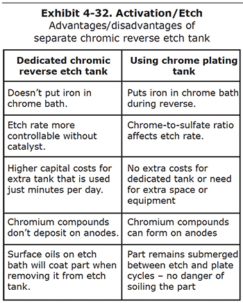
Dedicated Reverse Etch Tanks
Some plating shops reverse etch the parts in the hard chrome plating tanks, while others set up a dedicated, separate etch tank that has chromic acid and no catalyst. There are pros and cons to each of these setups, which are discussed below and summarized in Exhibit 4-32.
Reverse etching steel parts will dissolve iron and other components of the metal. These are soluble, and build up in the bath over time. Iron is the most common metallic impurity in a hard chrome plating bath, and leads to plating problems that are described in Section 6 of this course.
Some plating shops believe that the damage done to the chrome plating bath warrants the high expense of installing a dedicated chromic acid reverse etch tank. Other shops feel the cost is too high, or they may not have the necessary space to accommodate another tank over their secondary containment pit.
Some shops want to get as much control over the etch process as possible, and don't want the sulfuric, fluoric or other plating catalyst to influence the etch rate. They may then decide to install a dedicated etch tank.
One of the biggest problems with the use of a separate etch tank is that the surfaces of a cleaned and etched part may become fouled again if the surface of the etch bath or plating bath has any oily films or other floating debris. This contamination occurs when the part is raised from the etch tank or lowered into the plating tank. Since there is no reverse etch performed in the plating bath, defects may arise in the chromium deposit.
Both reverse etching in the plating tank and the use of a dedicated etch tank are common practices. Each shop should evaluate the pros and cons and decide which of the two systems is best for their facility.
Acid Etch
Acids other than chromic acid are sometimes used to activate and etch parts before hard chromium plating. For example, some aerospace specifications call for etching in sulfuric or a blend of sulfuric and hydrofluoric acids. These acids are suited to high-strength, heavily-alloyed and corrosion resistant steels. Occasionally, hydrochloric acid is used.
The non-chrome acid etch tanks may be immersion tanks, or they may be electrified with direct current to provide an electroetch capability. For example, stainless steels are usually electroetched cathodically, in which the part is made negative, which is more effective than simple immersion etching. Some other steels can be electroetched anodically.
Thorough rinsing is important if non-chromic acids are used for etching. If foreign acids are dragged into the hard chrome plating bath on the surface of parts or racks, they may upset the delicate chrome-to-catalyst ratio for the plating bath, or may lead to pitting or other damage to the plated parts. Hydrochloric acid is particularly dangerous because chloride contamination of the chrome bath is harmful even at very low levels.
Chrome Plating
In this section we will cover some important topics that relate directly to the chrome plating process:
- Determining how much chrome to deposit
- Selecting a current density
- Determining how long to plate a part
- Examining factors that affect the chromium deposition rate
- Initial plating procedures:
- Part warm-up. Bringing the part up to tank temperature.
- Initial rectifier settings. Should you:
- start the rectifier at the desired setting?
- start it at a lower setting and ramp up the current?
- strike the part with a higher than normal current?
- Checking for gassing
- Which setting--amps or volts--to use for controlling the plating rate?
Determining How Much Chrome to Deposit
One of the issues confronting every plater for each part is: "How much chrome is needed?" The answer depends on many factors, as you will discover in the following paragraphs.
Plating thicknesses are easy to establish for newly manufactured parts since they are machined and ground to uniform sizes before plating. Therefore, every part in a given batch or lot will require the same chrome plating thickness. On the other hand, parts that are chrome plated for rebuilding or reconditioning often need different thicknesses of chrome. Before plating, reworked parts are ground as much as needed to remove various surface defects such as corrosion, scratches, and pits. The chrome plating thickness must make up for any base metal removed, and this varies from part to part.
Nearly all hard chrome plated parts are ground/and or polished after plating to achieve the required finish dimensions and surface finish. In a minority of applications, the chrome plated part is placed in service "as-is," with no postplate grinding or polishing. This is referred to as "plating to finish size." One example would be the chrome plating of the bores of railroad car bearings, which may be plated with only 0.0002" to 0.0007" of hard chromium as a part of their rebuilding process. Plating to size is typically limited to thin deposits, since chrome tends to become more uneven as the deposit grows thicker and therefore requires grinding and/or polishing after plating.
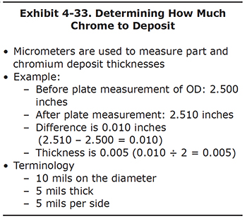
Most hard chrome is plated onto cylindrical parts. One potential error that new platers make is to forget that when the part is cylindrical, chromium is being deposited around the entire diameter of the part. Therefore, when the thickness of the part is measured with a micrometer, the chromium is actually only one-half as thick as measured.
To avoid confusion, let's look at an example (Exhibit 4-33). A piston is measured before plating using a micrometer and the reading is 2.500 inches. The piston is chrome plated and after plating the measurement is 2.510 inches. The difference between the before plating and after plating measurements is 0.010 inches. The thickness of the chromium deposit is one half of the difference in measurements, or 0.005 inches. This is equivalent to 5 mils.
The terminology used to discuss chrome thickness varies from shop to shop. If someone says they plated 10 mils of chromium on a piston, it could be interpreted either as 10 mils around the entire diameter or 10 mils thick.
In this course, when talking about chromium thickness, we will try to be consistent with the terminology. For this example, we would say that 10 mils of chromium were plated on the diameter or that the chromium is 5 mils thick. Another common way of referring to the thickness is to say that the chromium is 5 mils per side.
Let's look at two examples of calculating how much chrome to deposit (Exhibit 4-34).
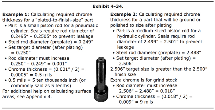
In the first example, we are plating to finish size. In this case, calculating the required chrome thickness is easy. Just subtract the preplate size from the finish size.
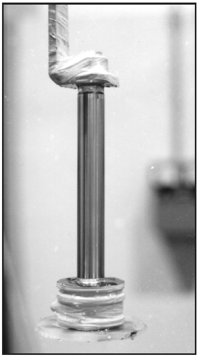
The example shows a small piston rod for use in an air cylinder. The seals allow only a one thousandth of an inch variance in the size of the rod to prevent air leakage. The plater chooses to set the middle of this range, 0.250 inches, as the target dimension for the plated part. The precision-ground steel part measures 0.249 inches before plating. The diameter must increase from 0.249 inches to 0.250 inches during the plating cycle, for a total diameter increase of 0.001 inches.
Therefore, 0.0005 inches or ½ mil of chrome thickness is required in order for the diameter of the piston to increase 0.001 inches.
0.0005 inches is usually referred to as "5 tenths" of chromium. This is short for 5 ten-thousandths of an inch.
This time, let's plate a piston rod for a hydraulic cylinder with a preplate diameter of 2.488 inches. It will be ground after plating to achieve the desired finish size.
The finish size is 2.500 inches, but we want to plate some extra chrome to be removed by grinding process. The additional thickness of chromium is referred to as grind stock. The plater has determined by previous plating cycles of similar parts that the grinder needs an extra 3 mils of chrome thickness, which is 6 mils on the diameter, to ensure that the grinding operation will produce a finished part that is the desired dimension. The target dimension is therefore 2.500 inches + 0.006 inches = 2.506 inches.
In order to calculate how much chrome is needed, first subtract the unplated steel diameter from the target or plated diameter. 2.506 inches – 2.488 inches = 0.018 inches. The required chrome thickness = 0.018 inches ÷ 2 = 0.009 inches, or 9 mils.
The amount of grind stock needed depends on the uniformity of the chromium deposit, the grinding machines used, and the technique and ability of the grinder. Although you want to stay on the safe side and always provide sufficient grind stock, you don't want to go overboard, which is a waste of plating time, chromium, and grinding labor. To optimize your efforts, maintain good communications with the grind shop and decide together how much grind stock is needed.
Generally, chrome deposited using conforming anodes requires about one-half to two-thirds as much grind stock than chrome deposited using stick anodes. That's because you get a much more uniform deposit with conforming anodes.
Selecting a Current Density
In nearly all cases, a plater should strive to achieve a bright chromium deposit. Bright deposits have been proven to be harder deposits and they provide the greatest wear resistance, two key attributes of hard chrome. Other deposit appearances such as milky, hazy, frosty and burnt are generally a sign that one or more plating parameters are not correct.
Although there are a number of factors that influence chrome appearance, the most influential are current density and bath temperature:
- Current density is the amount of current being applied to the part, divided by the surface area being plated. If you are plating a 100 in2 surface with a rectifier setting of 400 amps, then the current density is 4.0 amps per square inch (APSI).
- The bath temperature is usually held constant by a heating and cooling system connected to a controller that can
be set at different temperatures. Most facilities maintain hard chrome baths between
130-140°F. The main effect of raising the temperature is to allow the use of higher current densities without burning the deposit.
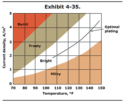
The relationship of current density to temperature is shown in Exhibit 4-35. Note that the values shown in Exhibit 4-35 are for standard single catalyst chrome baths containing 33 to 53 oz/gal chromic acid. For other bath formulations, consult your chemical supplier. They should be able to provide you with a similar graph.
In the graph, you can see that bright chrome deposits can be attained at various current density and temperature settings. To be safe, it is best to operate in the center of the bright range, which is shown by the optimal plating line. Operating out of the bright range is the most common cause of poor chrome appearance.
Most hard chrome plating is performed in the temperature range of 130 to 140 °F. To be in the middle of the bright range at 130 °F, you would plate at a current density of 3.0 APSI. At 140 °F the center of the bright range is 3.7 APSI.
A common unit of measure used by chrome platers in most other countries is the micron (µ). A micron is one millionth of a meter or one thousendth of a millimeter, which makes it smaller than a mil. To convert from mils to microns, multiply by 25.4. For example, convert 10 mils to microns:
10 mils x 25.4 = 254 µ
To convert microns to mils, multiply by 0.3937. For example, convert 60 µ to mils:
60 µ x 0.03937 = 2.36 mils
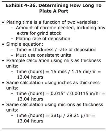
Determining How Long To Plate A Part
After determining the amount of chrome thickness needed on a part, you can calculate the plating time required. The only other piece of information needed is the plating rate of deposition, or in other words, how much chromium is deposited per hour (Exhibit 4-36).
The plating rate varies with many factors, but for a particular part and anode combination in a given bath, the most influential factor is the plating current density – the number of amps used per square inch of surface being plated.
The plating rate increases with higher current density. This doesn't mean that you should just strive for faster rates. Excessively high current densities may deposit chrome quickly, but there is a high likelihood that the deposit will be burnt, treed, or soft. As a general rule, most hard chrome plating is performed at current densities in the 2.0 to 4.0 amps per square inch (APSI) range.
Typical chromium deposition rates are 0.50 to 0.75 mils thick per hour for stick anodes, and 1.0 to 1.5 mils thick per hour for conforming anodes, using a conventional bath and average bright range settings (i.e., 130 °F, 3.0 APSI).
The best way to predetermine the plating rate is by analyzing previous plating logs. These logs should include preplate and postplate dimensions, plating times, plated surface area, and plating amperage and voltage. Procedures for establishing and using a plating log are presented in Appendix 5.
In order to calculate the plating time, just divide the target chrome thickness by the expected rate of deposition. It's important to keep consistent units for the desired plating thickness and rate of deposition. For example, if the thickness is in mils, be sure to use mils per hour as the rate.
Factors that Affect Rate of Chromium Deposition
Different hard chrome plating bath chemistries plate at different speeds. The high speed, non-etch baths can deposit chromium faster than the fluoride baths, which in turn, will plate faster than the conventional, sulfate-only baths. The differences in plating rate of deposition correlate with the cathode efficiencies for the baths. For example, a proprietary high speed, non-etch bath will have an approximate efficiency of 25%, the fluoride bath 20% and the conventional bath 12%. Higher efficiencies translate into faster plating speeds.
For any given bath chemistry, the plating current density is the single most influential factor affecting plating rate. For a given part and anode combination, chrome will plate faster with a current density of 4 amps per square inch than it will at 2 amps per square inch in the same bath. However, if a part is subjected to a current density that is too high, deposit roughness, burning or treeing may occur. These adverse deposit characteristics place a practical limit on the current density and plating speed.
The condition of the plating bath also affects the plating rate; a new bath will plate faster than older, contaminated ones. It is well known that the deposition rate of chrome decreases with the buildup of tramp metals (mainly iron, copper, and aluminum), trivalent chromium and other impurities in a hard chrome plating bath. Impurities increase the resistance of the bath, impeding the flow of electricity between the anode and cathode. Besides reducing efficiency, high levels of impurities increase the DC voltage required to pull the desired plating amperage. If a given part and anode combination requires 4 volts to achieve 2 amps per square inch with a clean bath, it may take 6 volts to pull the same amperage with a contaminated bath. Since wattage is the product of volts times amps, the power consumed with a contaminated bath can be much higher than with a clean bath.
The quality of the direct current from the plating power supply can affect the plating rate. Power supplies that have a high ripple may plate slower than heavily filtered power supplies or those with inherently low ripple.
Since the lead anode is an important electrode in a chrome plating cell, the condition of the anode will significantly affect the plating rate. In particular, anodes that are heavily scaled or have thick lead chromate films (yellow) will retard the plating process. Also, even clean anodes that are old tend to cause slower plating speeds, due to metallurgical changes in the lead alloy over time. Insufficient anode surface area and large anode-to-cathode spacing in a plating cell may also adversely affect plating speed.
Initial Rectifier Settings
There are basically three options at the start of plating. You can begin the plating process immediately at the desired amperage or voltage setting, you can start at a low setting and slowly ramp up the power until you reach the desired setting, or you can immediately strike the part with a high power setting at the start of plating.
Although you will hear many different opinions, under most conditions, using a ramp up or strike is not necessary.
For most parts you can start the chrome plating process at the desired amperage or voltage setting.
There are some exceptions and these are discussed in more detail later in the course. For now we will just list a
couple.
- When plating chrome on chrome, a ramp up procedure is absolutely necessary. This applies for example to parts that were removed from the plating tank and subsequently returned to the tank for additional plating.
- A strike is often used when low current density areas are present. A strike lasting several minutes helps to "throw" the chromium into those areas. Following the strike, the rectifier is set to the normal power setting.
Amps vs. Volts
When you chrome plate, you can adjust most rectifiers using either the amperage or voltage controls. Experts have been arguing about which is better since the chromium process was first commercialized around 1925. The truth is, there is no universal best way. It really depends on what you are plating and the equipment you are using.
In any case, it is a good idea to know how to plate both by amps and by volts. You might have process instructions that require you to plate by one method or the other, so you need to be prepared to deal with either one. Once you get a feel for the relationship between amps and volts, you will be a better chrome plater.
A thorough discussion of amps vs. volts is presented in Appendix 6.
Rinsing
Rinsing is an important aspect of chrome plating. If the parts and fixtures are not sufficiently rinsed, then when the plater handles the part, chrome solution is going to end up on the platers hands and clothes. Also, residual solution can cause staining and corrosion of steel parts. But, on the other hand, too much rinse water means higher operating costs and it impacts the environment.
Owing to the importance of this topic, a special section on rinsing is presented in Section 8 of this course. There, the focus is on reducing the amount of drag-out (chromic acid removed from the plating tank) and optimizing water use.
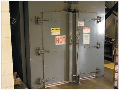
Exhibit 4-37. Bake oven used for hydrogen embrittlement relief. Courtesy of Delta Airlines.
Hydrogen Embrittlement Relief
Chrome plated parts are susceptible to a phenomenon known as hydrogen embrittlement. Hydrogen gas forms on the surfaces of the part during plating as a result of electrolysis, whereby water molecules in the bath are broken down into hydrogen and oxygen gasses. The oxygen forms at the anode.
Some of the hydrogen gas is adsorbed into the base metal. When this occurs, the fatigue strength of the steel is reduced so much that the part may fracture in service if the hydrogen is not released. This phenomenon is referred to as hydrogen embrittlement (HE) or hydrogen stress cracking (HSC). Hardened and high-strength steels are particularly susceptible to hydrogen embrittlement.
In order to drive out the trapped hydrogen and relieve stress, high strength steel parts are routinely baked right after plating (Exhibit 4-37). Military and aerospace specifications will specifically state how much time can elapse between plating and baking; usually it is 1 to 3 hours.
Specified bake times vary from 3 to 24 hours for most parts, and temperatures can vary as well, depending on the part and its service use. Baking ovens are designed to have minimal temperature variation over time, or even within the regions inside the oven. Usually, the ovens are fitted with temperature recorders, so that the plating shop can document the conditions experienced by the part during the bake.
In the event that a HE stress relief bake cycle is interrupted or stopped prematurely, part serviceability becomes suspect and the customer must be notified. Catastrophic failures may otherwise occur if the part is put into service.
Chromium Stripping
Facilities that receive used parts for refurbishment usually need to remove or strip the existing chromium deposits before plating the part. Also, new part manufacturers strip chromium from misplated parts.
Thin chromium deposits are sometimes mechanically removed by grinding; however, chemical stripping is generally the most economical method. Various solutions are used for this purpose, the selection of which is mostly dependant on the base metal. The most common procedures are discussed here.
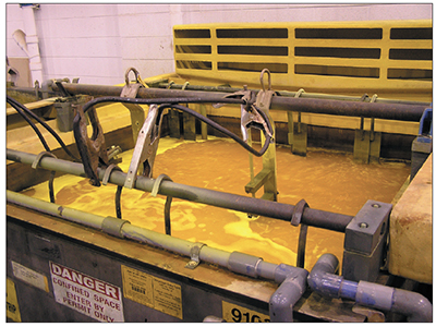
Exhibit 4-38. Alkaline electro-strip tank with air agitation. Courtesy of Delta Airlines.
Alkaline Electro-Strip
Most steels are stripped in alkaline solutions containing sodium hydroxide and sodium carbonate operated at room temperature to 120oF with a rectifier setting of 4 to 6 volts (Exhibit 4-38). These baths can be made up from raw chemicals or purchased ready for use. Some etching of the base metal can occur if pockets of solution become depleted of chemicals. Therefore, continuous agitation is recommended. Inhibitors may also be added to the solution to reduce etching.
The electro-strip process is operated anodically, meaning that the part being stripped is the anode (positive). The tank walls are often connected to the negative side of the rectifier and serve as the cathode. Because the strip tank chemistry is not conducive to plating, no chromium deposition occurs on the tank walls. The process of chromium stripping can be time consuming, especially when thick deposits are present. Stripping time can be reduced up to 75 percent by using conforming cathodes instead of the tank walls (Exhibit 4-39).
Acid Immersion Strip
Hydrochloric acid (also referred to as muriatic acid) is also used for stripping chromium. Copper alloys, stainless steels and tool steels are typically stripped in these solutions. An inhibitor such as glycerin or Rohamine B is typically added to the acid solution to limit the attack of ferrous metals. The immersion acid bath is operated from room temperature to 110 °F and no current is applied. High strength steels are subject to hydrogen embrittlement during acid immersion stripping and therefore must be subsequently baked.
Plating on Special Base Metals
Most hard chromium is plated on carbon steel parts, but at one time or another, you will be asked to plate on other base metals. The following discussion covers plating on some common materials other than carbon steel:
- Plating on existing hard chromium deposits,
- Plating on cast iron,
- Plating on aluminum, and
- Plating on stainless steel
Plating Chrome-On-Chrome*
(*Check your specifications to be certain chrome on chrome plating is permissible.)
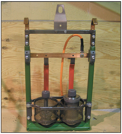
Exhibit 4-39. Conforming cathode stripping rack for aircraft parts. Courtesy of Advanced Tooling Corporation.
Many platers still believe that you can't effectively plate chrome on chrome, when actually, it can be a lot easier than plating on some steel alloys. However, it's important to follow procedures that will allow the new chrome to bond to the existing chrome layer.
First of all, the outer surface of the part must be the same temperature as the bath. This is accomplished by placing the part in the chrome bath without the rectifier being turned on and simply allowing the heated bath to warm up the part. For large parts, a 30-45 minute warm-up period is often necessary; for small parts, 5 to 15 minutes is sufficient.
Next, the existing chrome must be etched. This is usually the tricky part, because the age and condition of the old chrome will vary. If the preexisting chrome layer is under-etched, the new chrome will peel. If it is over-etched, the existing chromium will be damaged because the reverse current and chromic acid will electrostrip more chromium in the vicinity of the microcracks, which tends to widen the crack structure and make it unsuitable as a base layer. Unfortunately, there isn't a single rule that works for all parts. For example, two minutes at 2 amps per square inch is commonly used, but it won't always be correct.
Here's a way to increase your chances for success. Turn off the air or fluid agitation to the bath temporarily so that
the surface of the solution becomes still. Begin reverse etching the chrome plated part at a current density
of 2 APSI. Observe the surface of the plating bath above the part. At some point – it might be 30 seconds or 2
minutes – you will see a significant amount of hydrogen gas bubbles rising to the surface. Continue the etch for 60
seconds after the gassing becomes significant. If you can't turn off the air agitation, or cannot observe the
gassing, try etching at 2 APSI for 3 minutes.
This next step is very important. Even if you have warmed and etched the part properly, it may peel or blister if you begin plating new chrome at normal power levels from the rectifier.
When the forward polarity is first applied to the part and anode, the voltage and current must be lower than normal. The idea is to "wash" the part with hydrogen gas first, then slowly increase the power level to the point where chrome will deposit, and then slowly speed up the plating until it gets to the desired speed. This is called ramping up the power. If the ramp is too fast, or if full plating power was applied to the part immediately after the etch, the new chrome will not adhere well to the old chrome. However, ramping too slowly is not advised, because it deposits dull soft chrome in the first minutes, when the power level is too low for the bath temperature.
A good rule of thumb is to take 7 or 8 minutes to ramp from the initial 2.5 – 3 volts to the desired plating amperage.
Plating Hard Chromium on Cast Iron
Occasionally, you may be asked to plate a cast iron part and this can be a very frustrating experience unless you follow some guidelines. Examples of cast iron parts include cylinder liners for internal combustion engines and cast iron piston rings.
Cast iron is difficult to hard chrome plate because it is porous and usually has some non-metallic materials trapped in the pores, such as graphite or carbon particles. Hydrogen forms at these sites before chromium is deposited, which often leads to pits in the chrome.
If a cast iron part is treated like a steel part during the pretreatment and plating steps, it will probably have missed spots, or may not plate at all. Any chrome that does deposit may exhibit adhesion problems.
The following pretreatment and plating procedure below should help when plating on this difficult metal (rinse steps not shown):
- Solvent degrease and/or aqueous clean.
- Aluminum oxide grit blast.
- Place in chrome plating tank with immediate 2.0 volts forward polarity.
- Step up power 0.2 volts every 15 seconds until current density to part is 5 – 6 amps/in2 (APSI).
- Strike the part for 2 minutes at 5 – 6 APSI.
- Reduce the power level to normal current density (2.5 – 4 APSI) and plate to size.
The above steps are very important and should be performed diligently. Cleaning is followed by grit blasting, which prepares the surface for plating. The plating cycle does not include a warm up or reverse etch. The part should be subjected to a low power level as soon as it is placed in the tank. Start at 2.0 volts and ramp up every 15 seconds by 0.2 volts until a current density of 5 to 6 APSI is achieved. Using a higher than normal current density is referred to as a strike. It helps chromium deposition get started over the entire surface of the part. After two minutes, reduce the power level to a normal current density of 2.5 to 4.0 APSI.
Plating Chromium on Aluminum
This discussion covers a procedure for plating chrome on aluminum using the zincate process, which is so named because a thin zinc coating is applied to the aluminum part prior to chrome plating. The zinc coating prevents aluminum oxide formation before it is stripped off by the chromic acid; without this sacrificial coating, the chromium deposit would flake and peel off the aluminum part.
There are many variations of the zincate process in use today. One particular procedure is discussed here, but keep in mind that there are others that will work. In fact, you may find that one procedure works well for a particular aluminum alloy, but not for a different one. So, expect to see different processes in other shops and if you are setting up your own line, be prepared to experiment with the process before honing in on acceptable plating.
The procedure discussed here works well for a conventional chrome bath. When using proprietary baths, consult with the technical department of the chemical supplier.
During the zincate process, a thin film of zinc is applied to the aluminum part. This is accomplished using an immersion zinc bath rather than a zinc plating bath. With immersion zinc, the part is simply placed into the zinc bath and a film of zinc adheres to the aluminum surface. The thickness of the coating is controlled by the amount of time the part is immersed. With zincating, the thickness is critical; too little and the zinc will be removed well before chrome is deposited, and too much and the chromium will not adhere well. Also, the cleanliness of the aluminum surface is critical to the success of the process and therefore precleaning steps are necessary.
Another aspect of the process that makes it different from plating on steel parts is that aluminum parts coated with zinc must be connected to the power source before being placed in the chrome tank. That's because the thin zinc coating dissolves quickly in chromic acid and even a few seconds of soaking in the chrome bath will remove it. The process of putting a part in the tank with the power connected is sometimes referred to as going in "live" or "hot."
The aluminum plating line can be simple or more complicated depending on your workload and types of parts being plated. In cases where you have a limited number of parts, you may be able to get by with just vapor blasting for etching and cleaning, followed by zincate and chrome plate. Going this route will reduce the number of tanks needed, however, it has limited application and won't work well for a shop that receives a wide variation of aluminum parts.
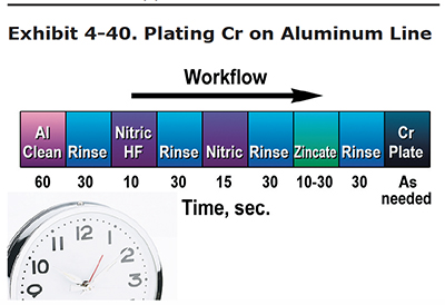
Exhibit 4-40 shows a chromium on aluminum plating line. Typically, the aluminum parts are grit blasted before they arrive at the plating line. If a mirror finish is required on the aluminum part, the grit blasting step is eliminated.
The process moves from left to right:
- Clean in an aluminum cleaner,
- Rinse,
- Dip in a nitric/HF solution,
- Rinse,
- Dip in nitric acid,
- Rinse,
- Zincate,
- Rinse, and
- Chrome Plate
Zincate Step. The thickness of the zinc coating is very important. If it is too thin, it will be dissolved in the chrome bath before chrome plating can take place. If it is too thick, it results in a soft coating that often produces a poor bond with the chrome. A mistake in either direction usually means peeling chrome. Also, the zinc coating should be smooth and even in color. If it looks blotchy, you should restart the process with the nitric acid dip step. In fact, some shops use a double zincate step. With this approach, the part goes through the nitric acid dip and zincate twice. The double zincate seems to provide a more even zinc coating.
Typically, an adequate coating of zinc is deposited in 10 to 30 seconds. However, immersion times can be as high as 5 minutes. You will need to experiment with your setup and you may need to change the procedure for different aluminum alloys.
Plating Procedure. The chromium plating bath will dissolve the zincate coating in a matter of seconds. Therefore, you must put the part into the chrome tank with the current on, in forward polarity. The rectifier should be preset to the approximate plating voltage/amperage before the part is immersed. There is no reverse etch step with plating on aluminum.
Plating times should be calculated the same way you do it for steel parts.
Plating Hard Chromium on Stainless Steels
300 series stainless steels, like 304 and 316, contain nickel. The nickel becomes passivated, and hard chromium will not adhere to it with a strong bond. At minimum, the 300 series stainless steels must be activated before plating. Some plating shops also follow the activation step with a Wood's nickel strike, which applies a thin layer of nickel between the activated stainless substrate and the chromium coating. A simple Wood's nickel strike bath contains nickel chloride and hydrochloric acid.
One possible process sequence is to clean or electroclean the part in an alkaline cleaning solution, rinse, immersion etch or electroetch in sulfuric, hydrochloric, or mixed acids (sulfuric and fluoride salts), rinse, then chrome plate. A nickel strike is sometimes used also.
If hydrochloric acid pretreatment steps are used, the plater should rinse quickly, but thoroughly, before immersing the part in the chrome bath. HCL is a serious contaminant for the chrome bath, even at low levels.
400 series stainless steels do not contain nickel, and are easier to plate with hard chrome than the 300 series steels. In one common method, the part is cleaned, rinsed, etched in a sulfuric-hydrofluoric acid solution, rinsed, then chrome plated.
Click here to take the Section 4 Quiz.